Physical Computing
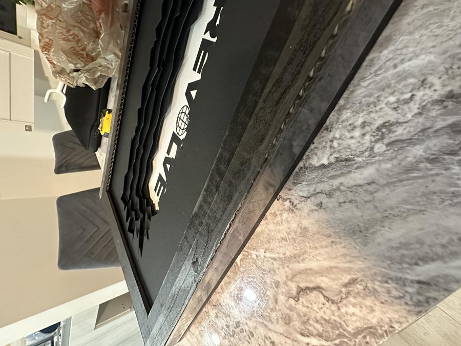
Remote-Controlled LED Desktop Lightbox (REVOLVE)
For my final project in Physical Computing of Spring 2025, I was tasked with either creating a new piece or refining a past project into a fully realized product. I chose to revisit my first project—an LED sign that spelled out "REVOLVE," the name of my record label. Rather than remake the sign entirely, I scaled it down to a desktop size that could be 3D printed in multiple parts and upgraded it to include a remote control sensor, eliminating the need to manually press the circuit board to turn it on.

Getting Started
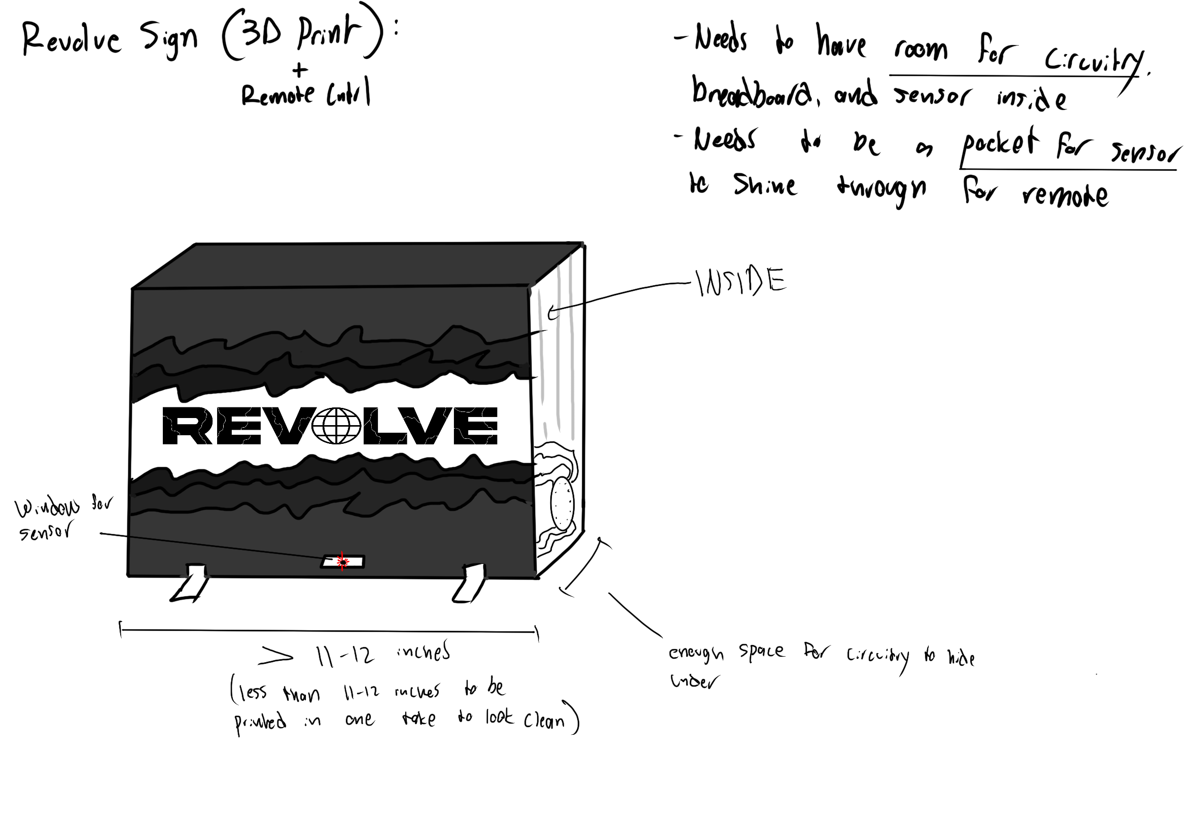
- Set design constraints based on 3D printer max dimensions (about 250mm width, depth, and height)
- Scaled down the original sign to fit within those limits
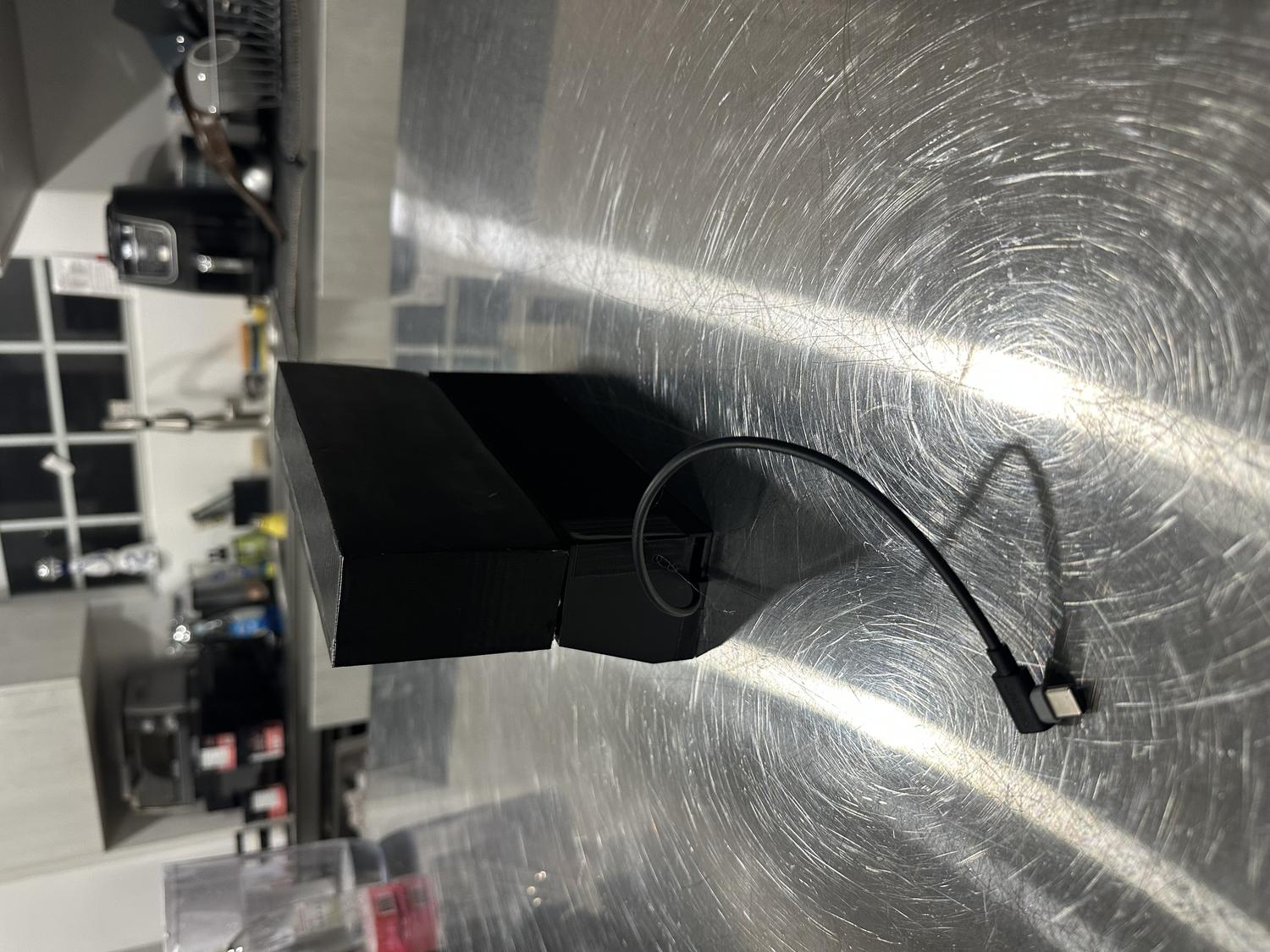
- Added a hole at the bottom so the infrared sensor could receive signals from the remote
- Made sure there was enough internal space to fit the circuit board and wiring
- No breadboard was needed—circuit worked with just the IR sensor and LED connections
Planning The Build
Materials:
- 3D printed material (PLA)
- Hot glue
- Black Duct Tape
- 8 x 1 mm Magnets
- Digital caliper
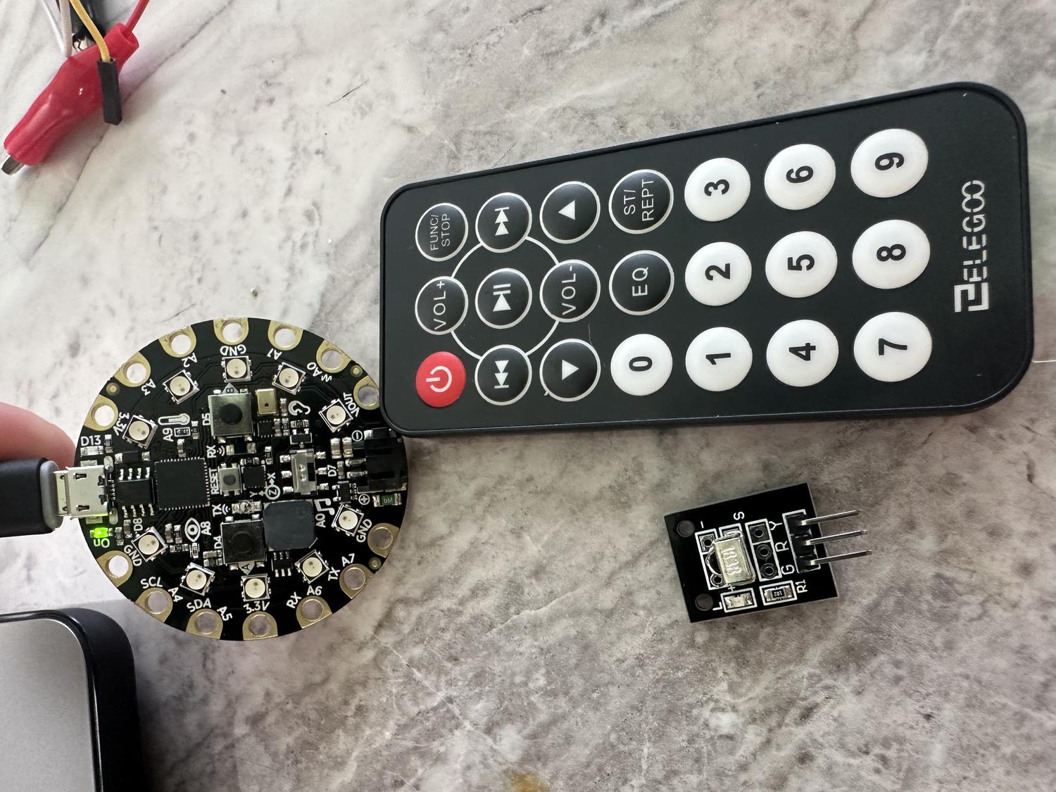
- Circuit Playground Express board
- Alligator to male wires
- Aligator to female wires
- 3X LED RGB Panels (8 x 8 Neopixels)
- IR Remote
- IR Remote Sensor
Steps:
- Measured each RGB panel - 80mm x 3 = 240mm
- Measured the circuit board - 50.7mm diameter
- Measured the IR sensor - 12.56mm tall
- Measured the sq ft of all wires together - 60mm x 65mm
3D Modeling
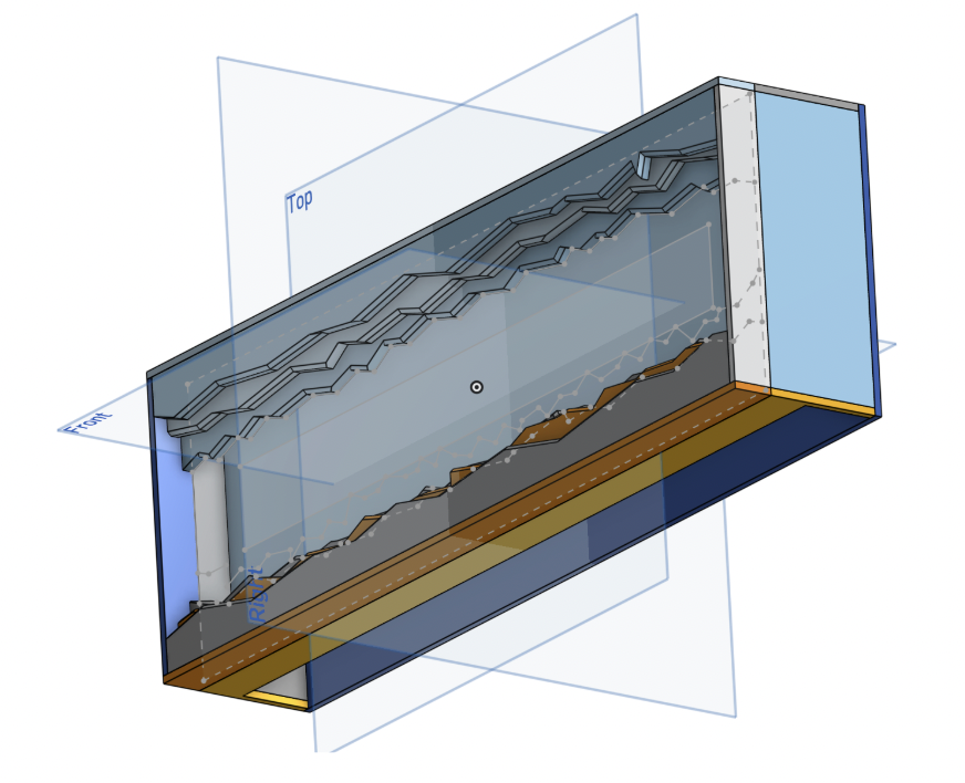
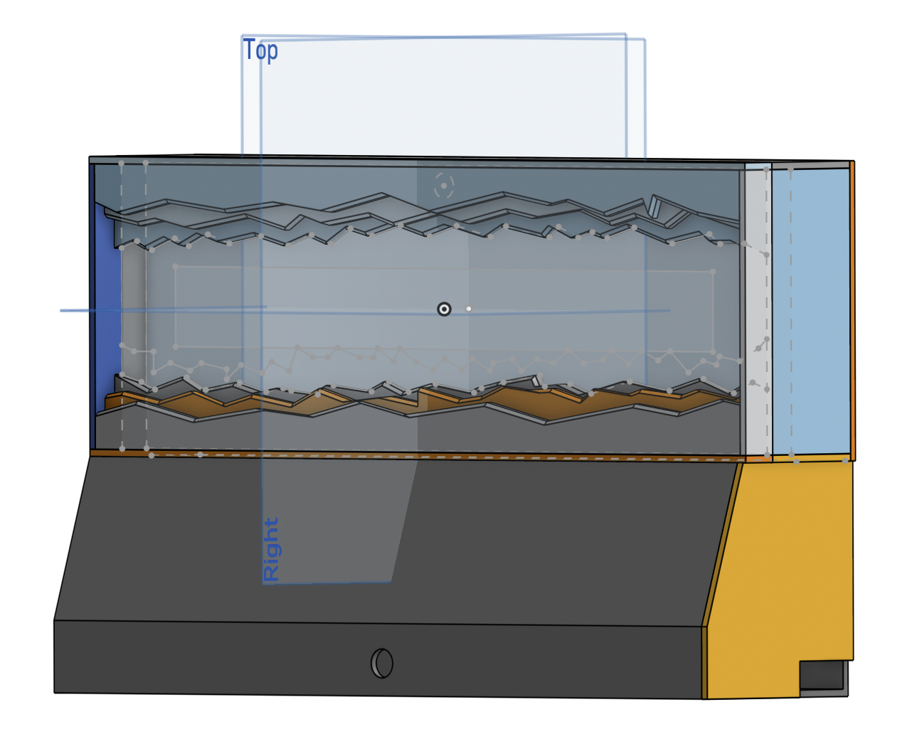
- Used Onshape to plan the build based on measured constraints
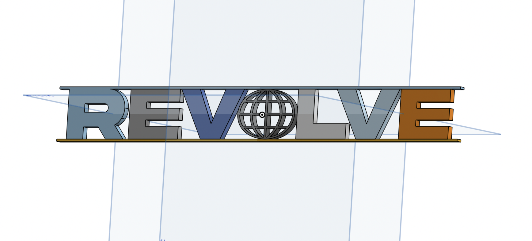
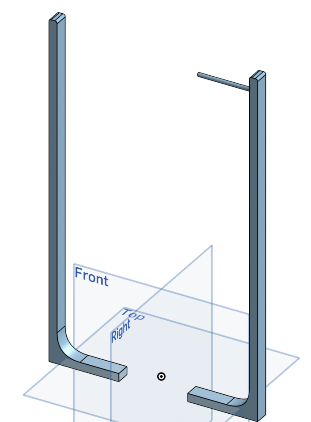
- Designed a front frame inspired by the original REVOLVE sign
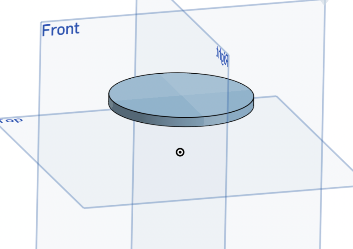
- Created a clear frame for the LED light to shine through
- Added spacers to support and align internal components
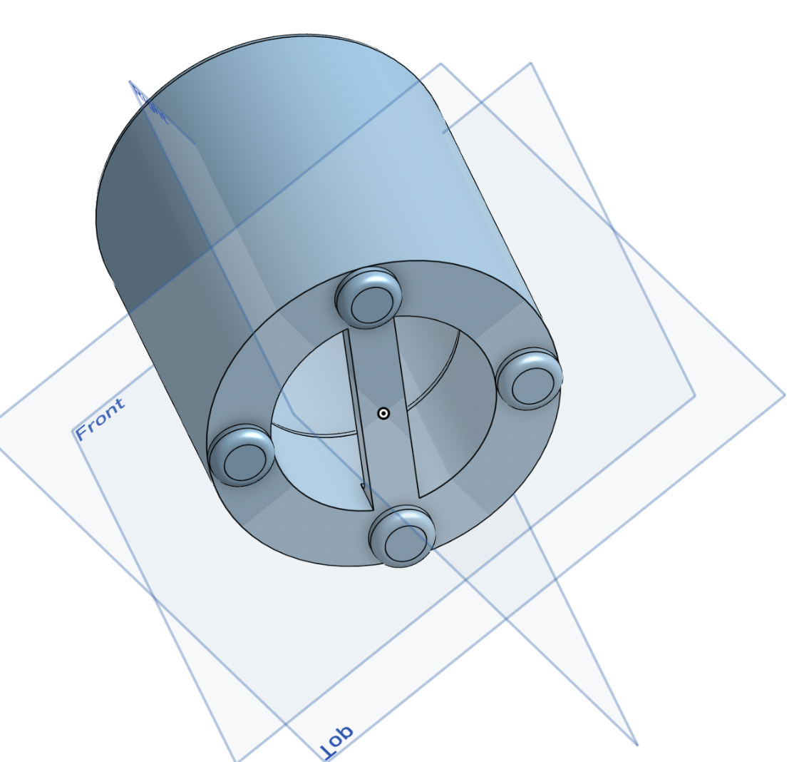
- Modeled the back panel to hold all electronics securely
- Left a gap at the bottom for wire routing
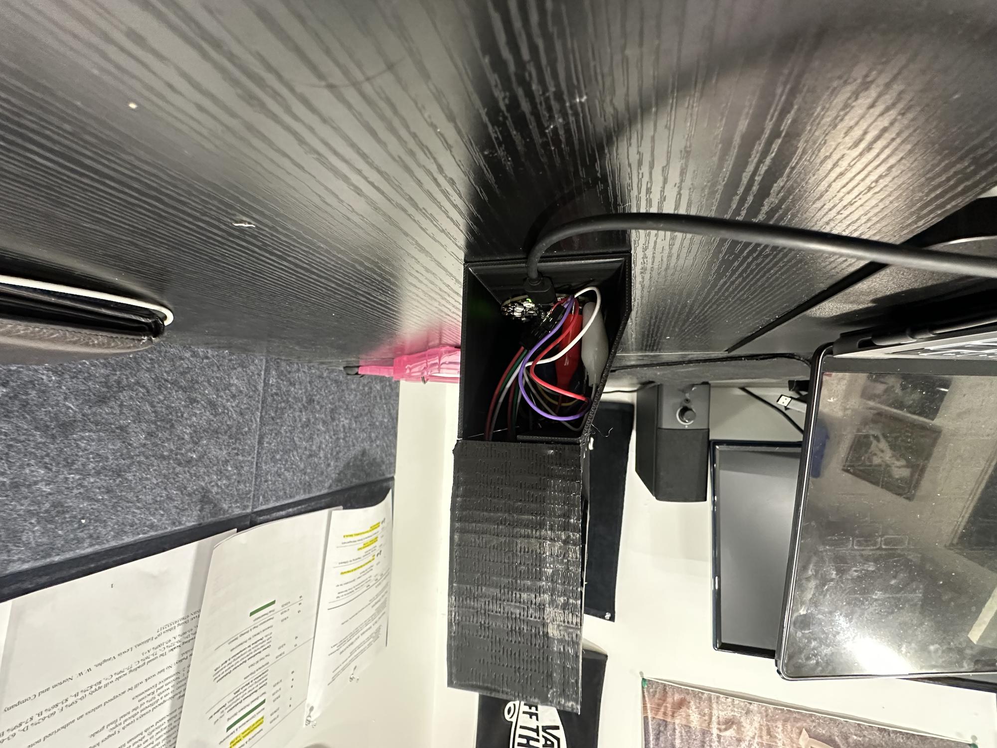
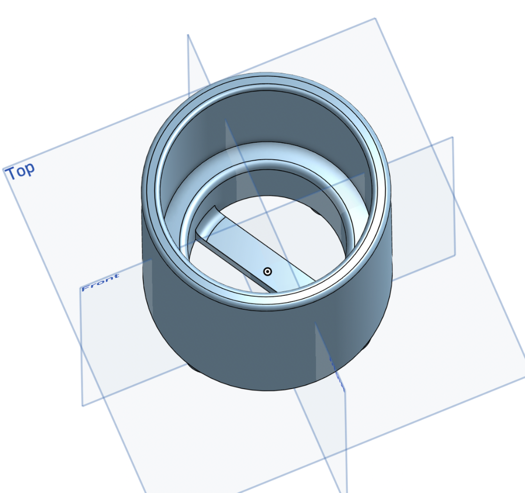
- Designed a bottom chamber to house the circuit board and sensor
- Included a small hole for the sensor and another for the power cord exit
- Used the chamfer tool to make the "underground" cuts and grooves look more chipped and cracked
Printing Process
- Imported five separate pieces into Bambu Studio for printing: front frame, clear LED cover, back holder, bottom chamber, and chamber door
- Separated the parts to allow for proper assembly after printing
- Added supports to the main compartment and spliced the file
- Exported the spliced file and began the printing process
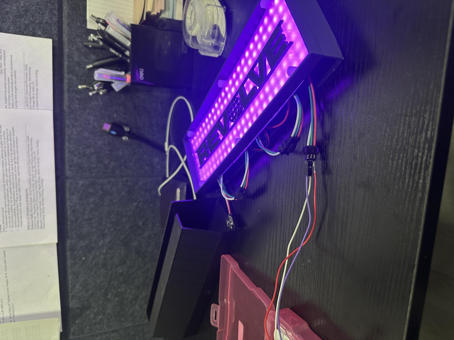
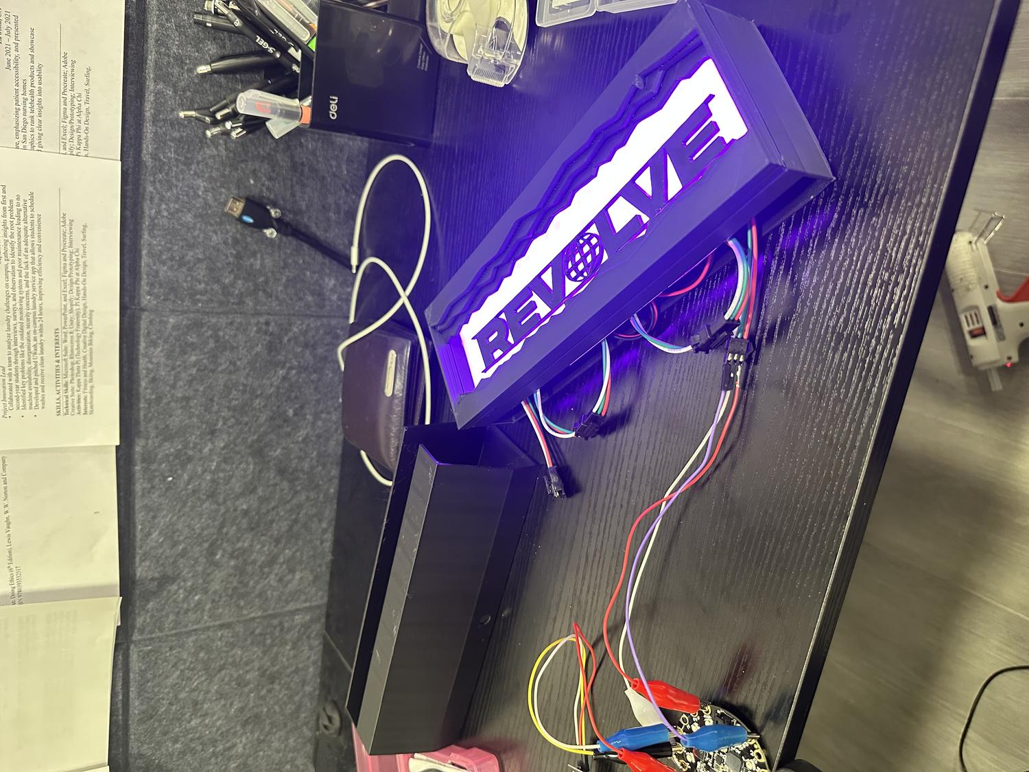
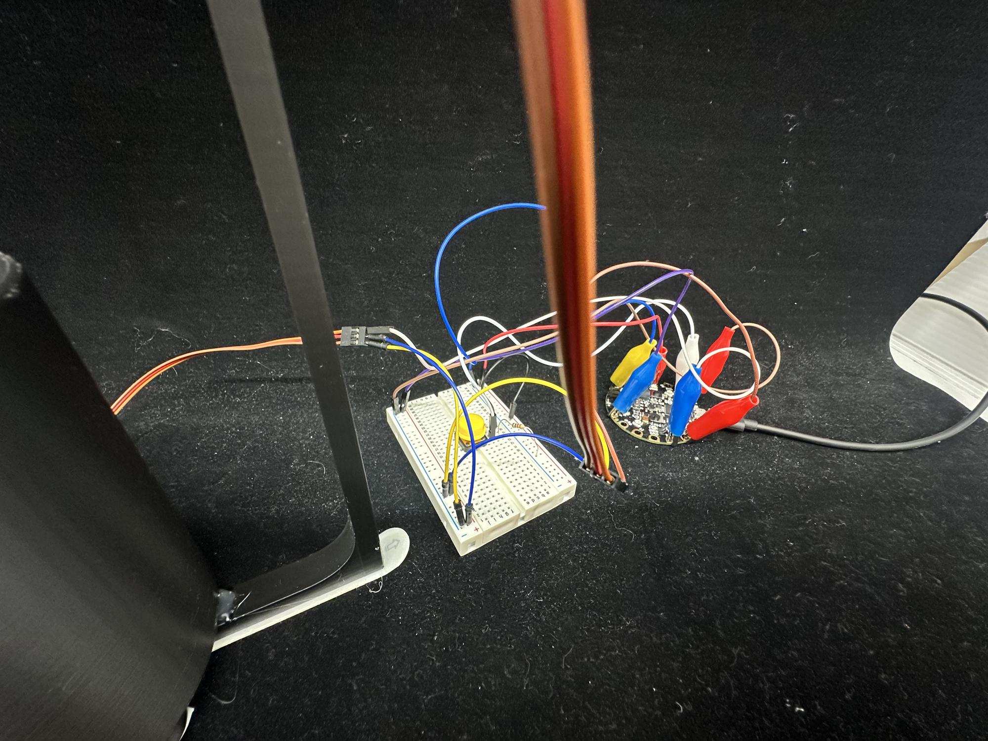
Wiring / Coding the LED Panel
IR Remote in Action
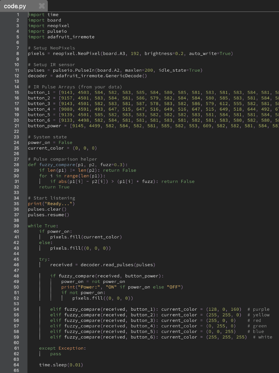
Python Code
- Used Mu Editor with a Python script to read IR remote pulse data via the terminal
- Collected pulse data for buttons 1–6 to assign six different colors to the panel
- Captured pulse data for the power button to toggle the device on and off
- Planned to include more features like LED chase effects, brightness control, and extra colors
- Limited RAM on the board (due to 192 NeoPixels) restricted how much functionality could be added
Inputs / Outputs:
| Inputs | Outputs |
|---|---|
| Power Button | Turns device on or off |
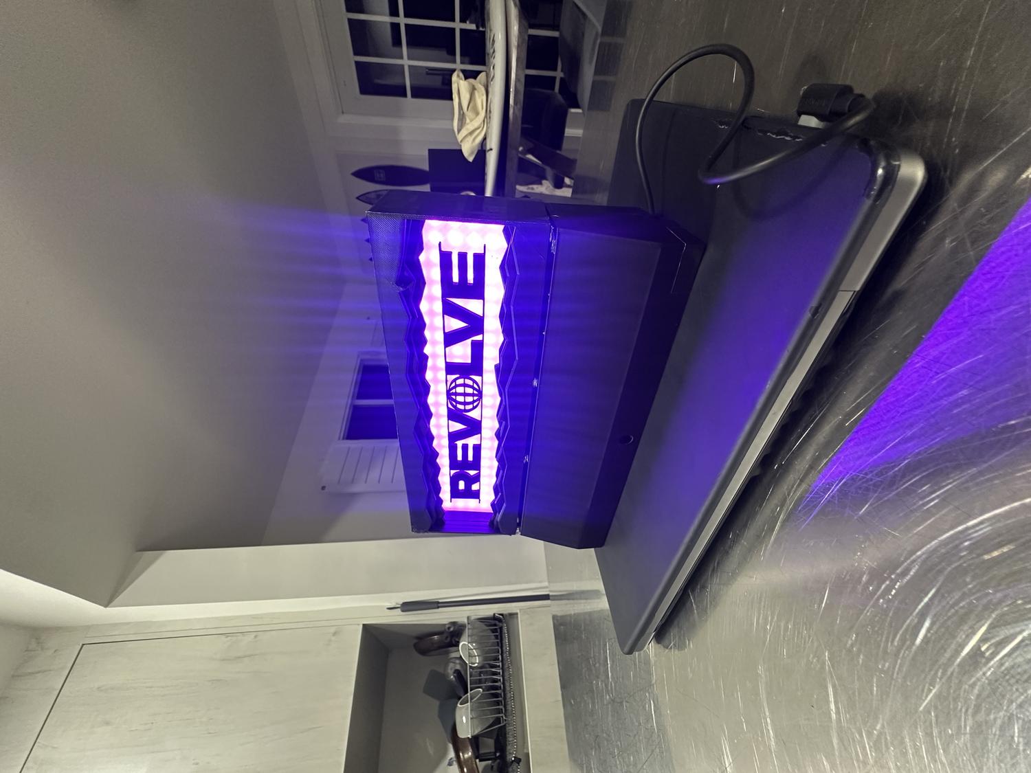
| Button 1 | Makes neopixels purple |
| Button 2 | Yellow |
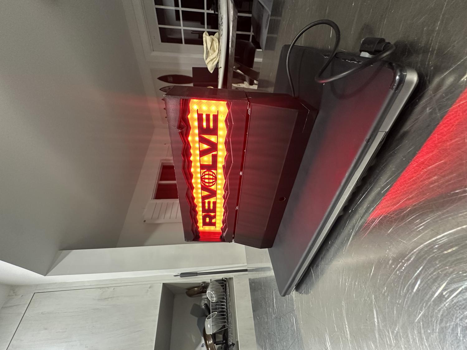
| Button 3 | Red |
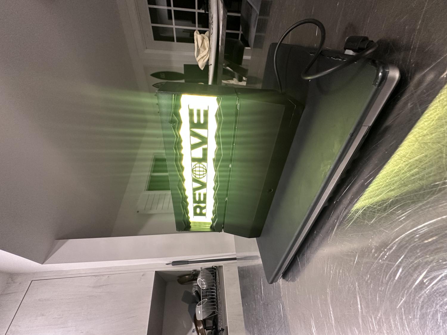
| Button 4 | Green |
| Button 5 | Blue |
| Button 6 | White |
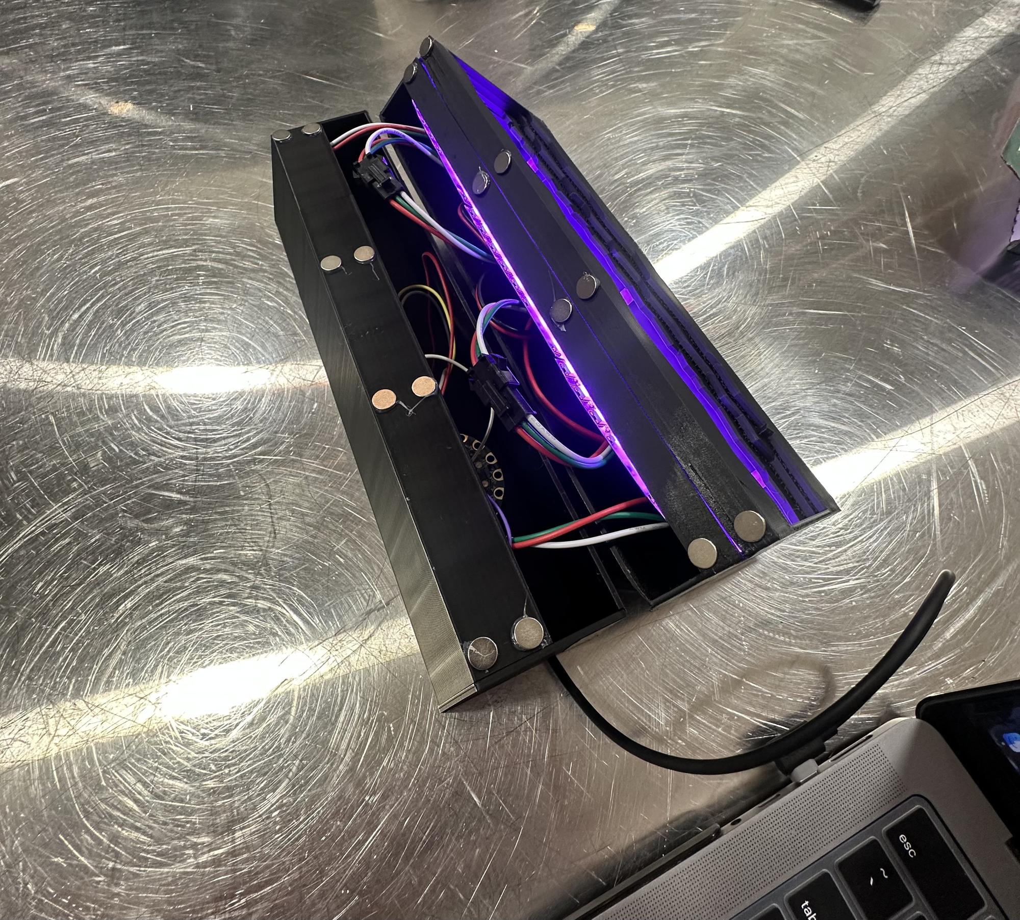
Assembly
- Pieced together all three NeoPixel LED panels and taped down the wires to save space
- Attached the LED panels to the clear PLA frame and began visualizing the full assembly
- Hot glued the REVOLVE letters to the center of the clear frame
- Fit the clear frame snugly into the back holder
- Placed the main front frame over everything and secured it with black duct tape to hold it precisely and cover separation lines
- Fed the IR sensor into the bottom chamber and secured it with duct tape in front of the sensor hole
- Inserted the rest of the circuitry, making sure everything fit neatly inside
- Added 8 magnets to the bottom chamber and 8 to the top frame so the pieces could clip together securely but still be easily disassembled
- Attached a side door to cover the bottom chamber opening, using duct tape while leaving space for the power cord to feed out
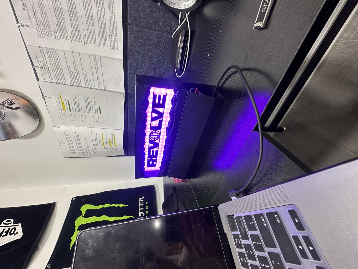
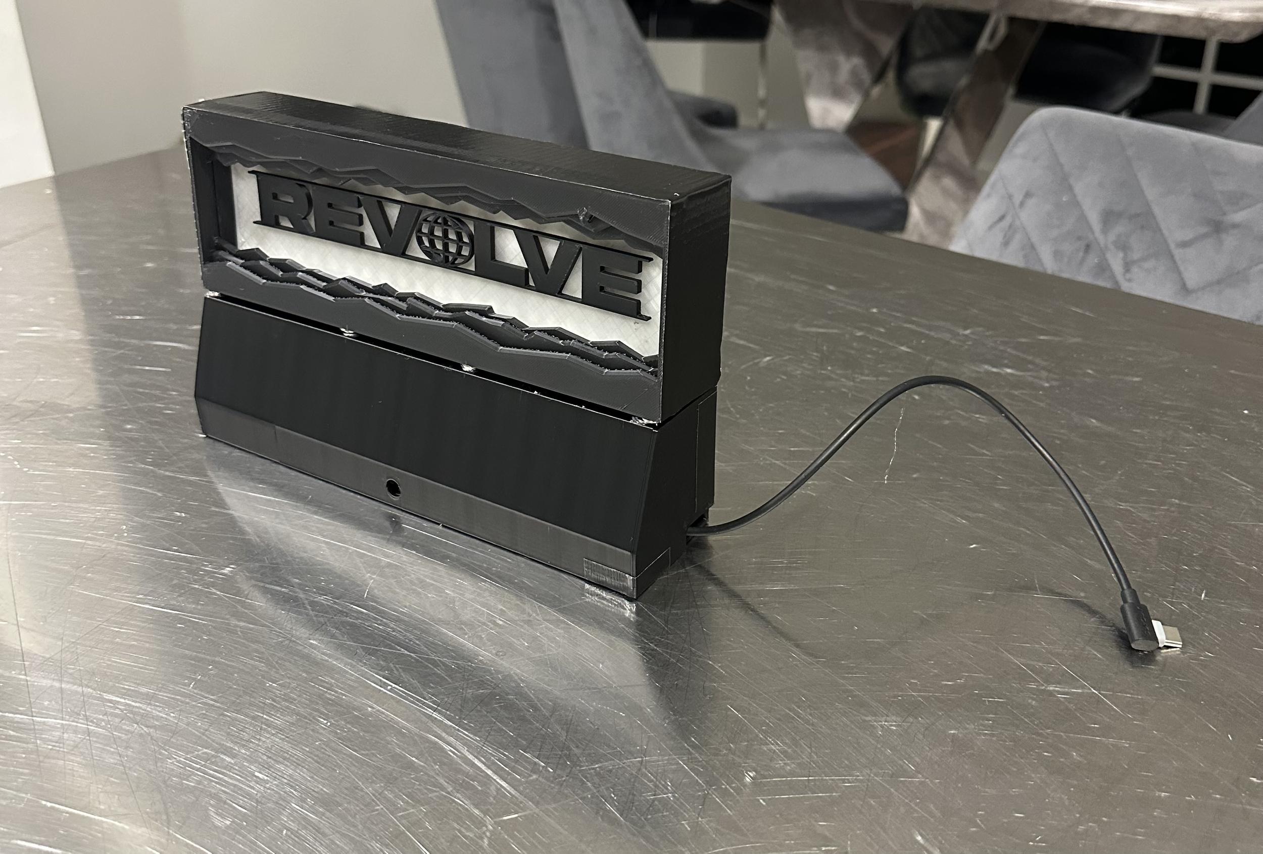
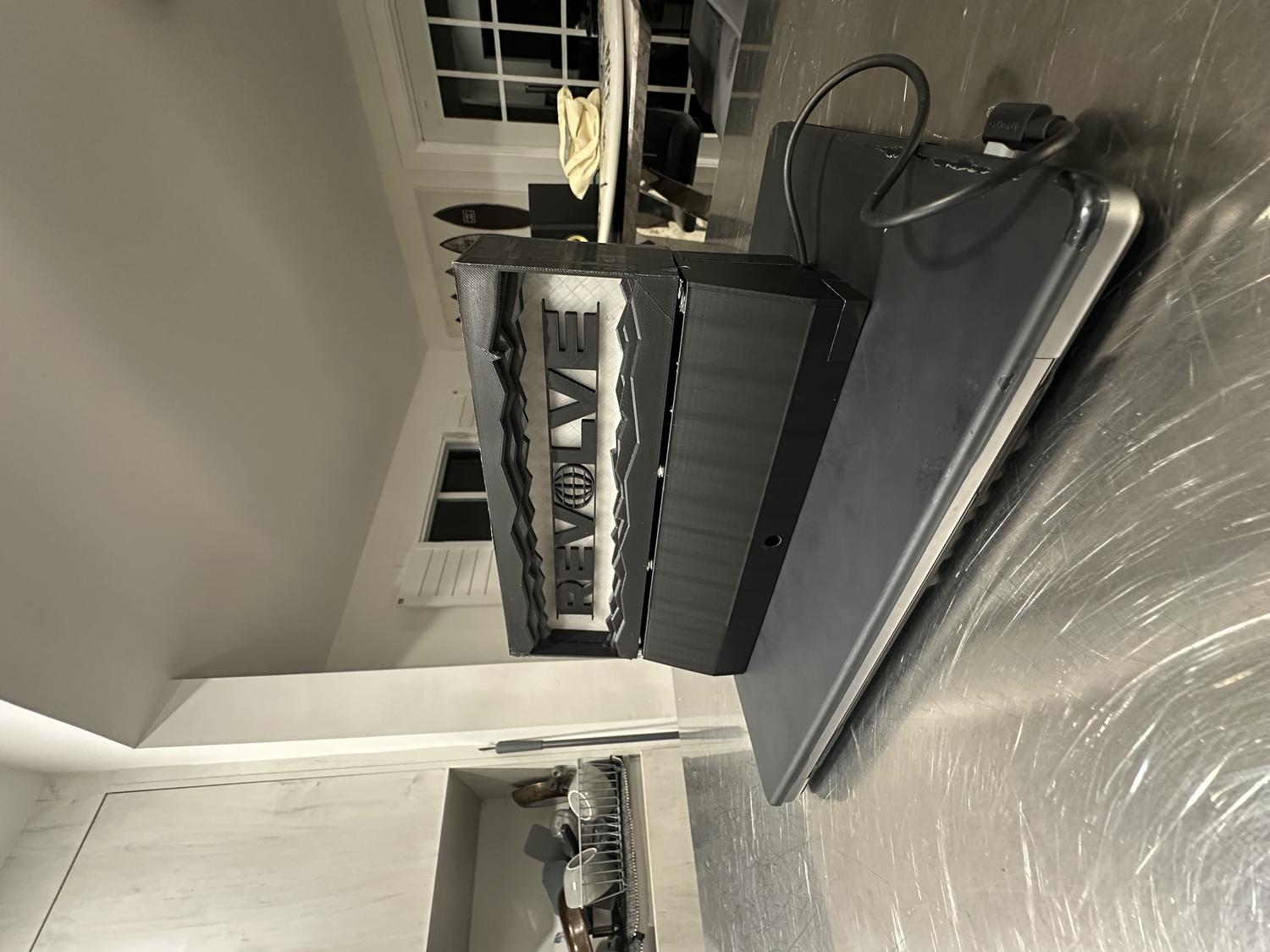
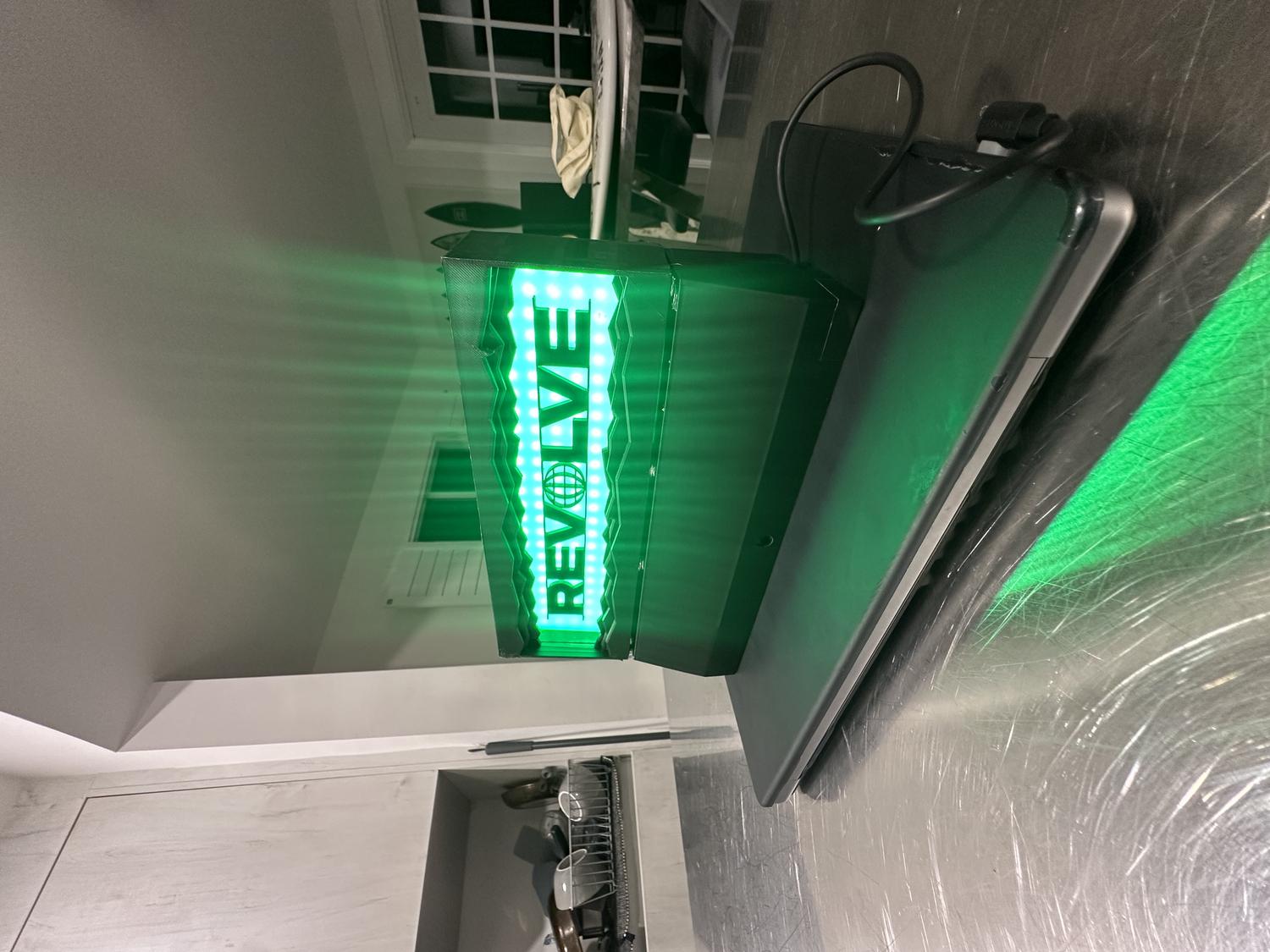
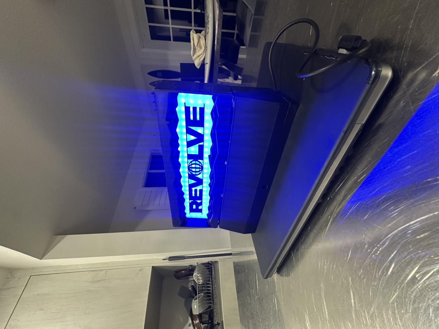
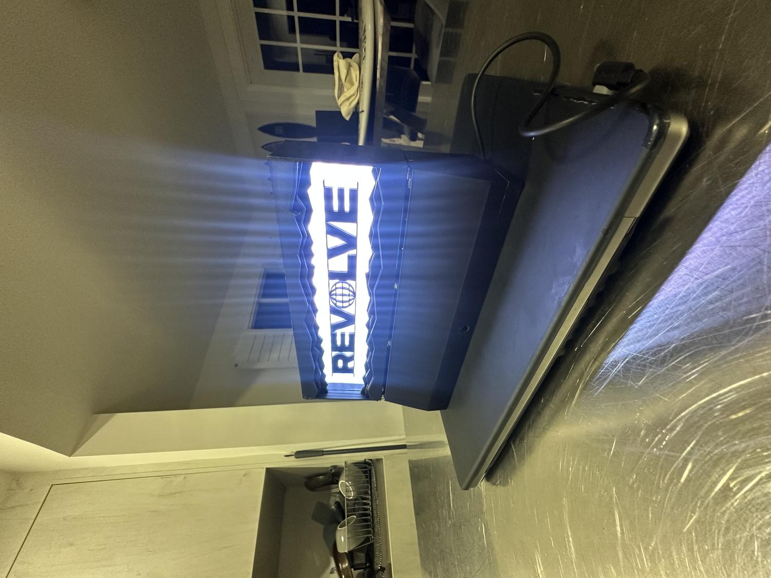
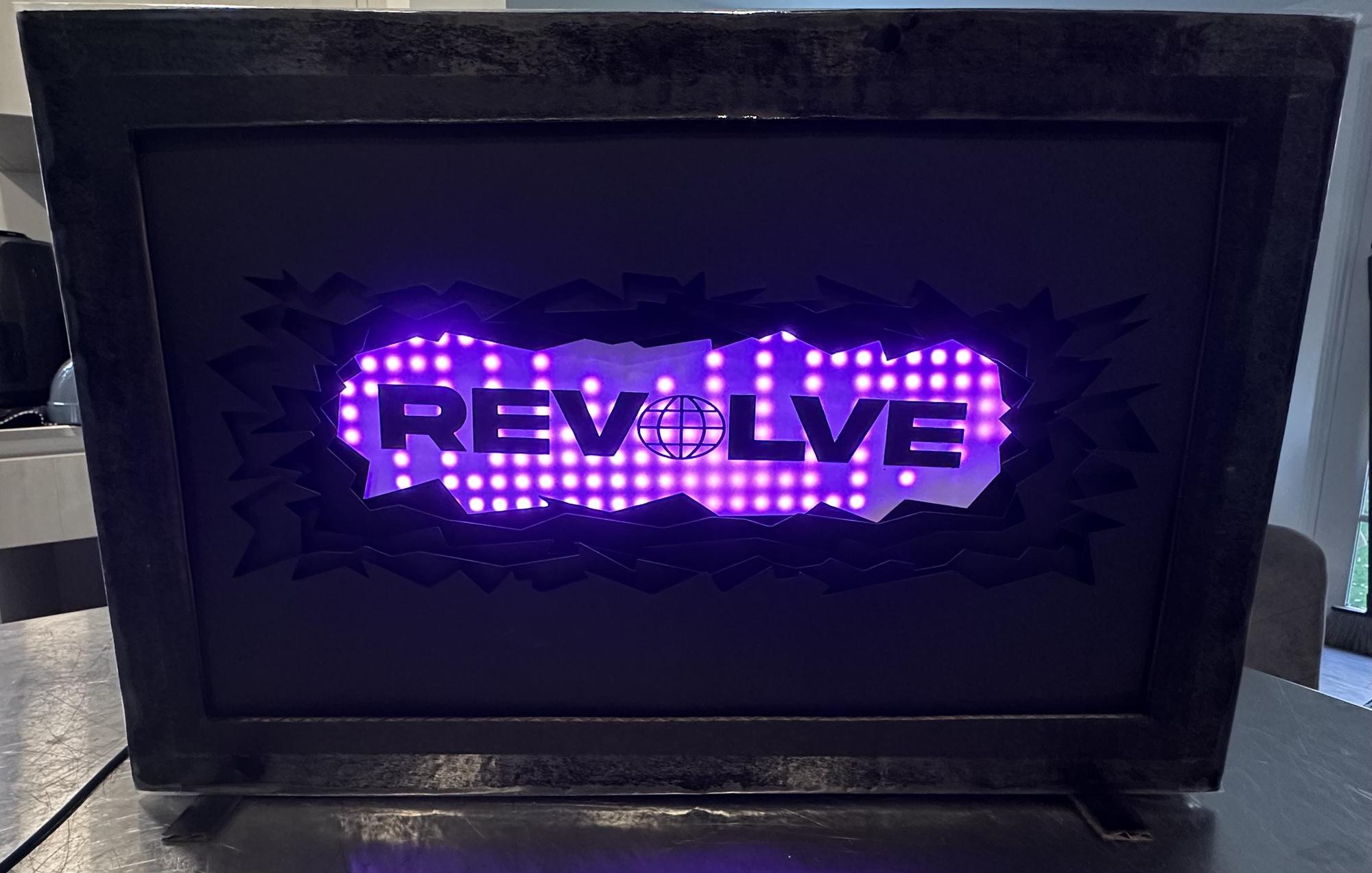
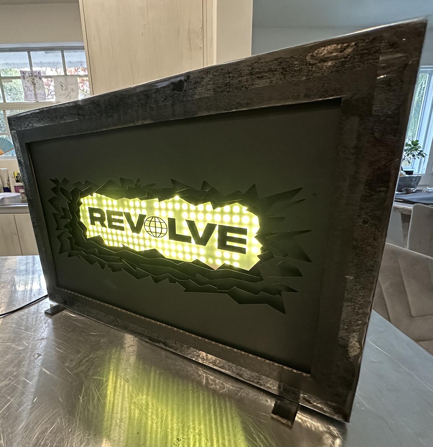
Finished Remote-Controlled Desktop Lightbox

Reflection
What Worked Well:
- The prints came out clean with minimal warping—each piece fit as intended
- The IR sensor functions reliably from 5–10 feet away
- The LEDs shine clearly through the clear PLA and create a strong visual effect
- All hardware fit perfectly in the bottom chamber without feeling cramped
- The magnets are both functional and visually clean, helping the device stay secure
- The final design matched the original vision and looks aesthetic on any desk
Challenges & Limitations:
- Limited RAM on the circuit board restricted the number of features that could be added via remote control
- Originally aimed to use 9 remote buttons for color selection, brightness control, and NeoPixel animations
- The 192 NeoPixels and IR pulse data consumed most of the circuit board's RAM
- Adding more functionality caused the board to overload and crash
- Settled on 6 color options with on/off capability, which was still satisfying
Takeaways:
- Future iterations could use a board with more RAM to support expanded features like animations and brightness control via remote
- The goal was to revise my original REVOLVE LED wall sign (approx. 19"×12") made from cardboard and Cricut-cut letters
- This version was scaled down, 3D printed, and fully enclosed to resemble a polished, functional product
- The final piece is durable, cleanly assembled, and visually high-quality
- Thorough planning led to a result that exceeded expectations
- Future versions could support more remote functions with additional inputs/outputs
- Despite hardware limitations, this was a successful and complete first prototype that met all core design goals
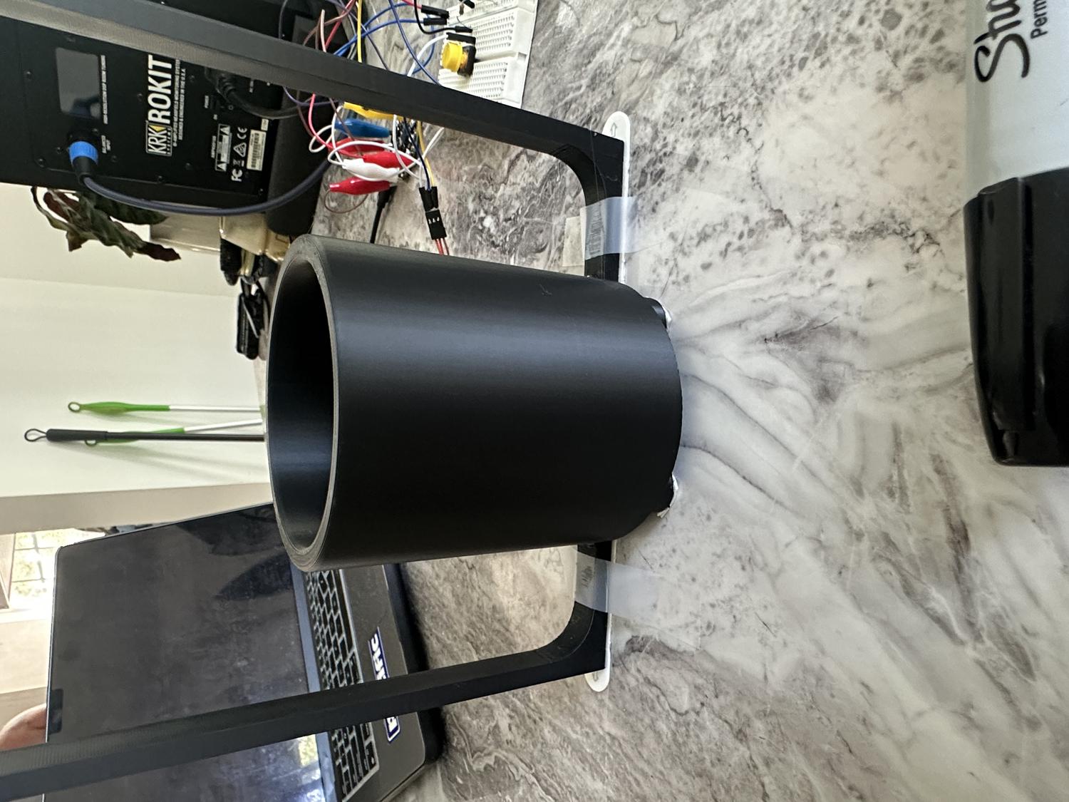
Electrolyte Robot
For our second project in Physical Computing for Spring 2025, the goal was to design and build a device that either helps or humorously doesn't help with a daily task. We were required to include at least one input, one output, and a 3D-printed component designed by us.
I decided to focus on something I do every day: mixing electrolytes into water. Normally, I unscrew the container, scoop the powder, pour it into a glass, and stir it with a spoon. It's a simple task, but one that felt like the perfect opportunity to automate. I set out to design a device that could dispense the electrolytes into the water and stir the contents thoroughly without the use of any sticks or spoons going into the liquid—essentially a mini robot version of my daily routine.
The idea pushed me to explore 3D printing in a more advanced way, as well as work with servo motors, breadboard circuitry, buttons, and Python code using the Adafruit Circuit Playground Express. The result was a fully functional prototype that, despite the power limitations of the motors, successfully carried out the task. This project became a great test of my planning, creative thinking, and technical execution—and ultimately, a rewarding example of how hardware and code can work together to solve real (or not-so-real) problems.
My daily task
Getting Started
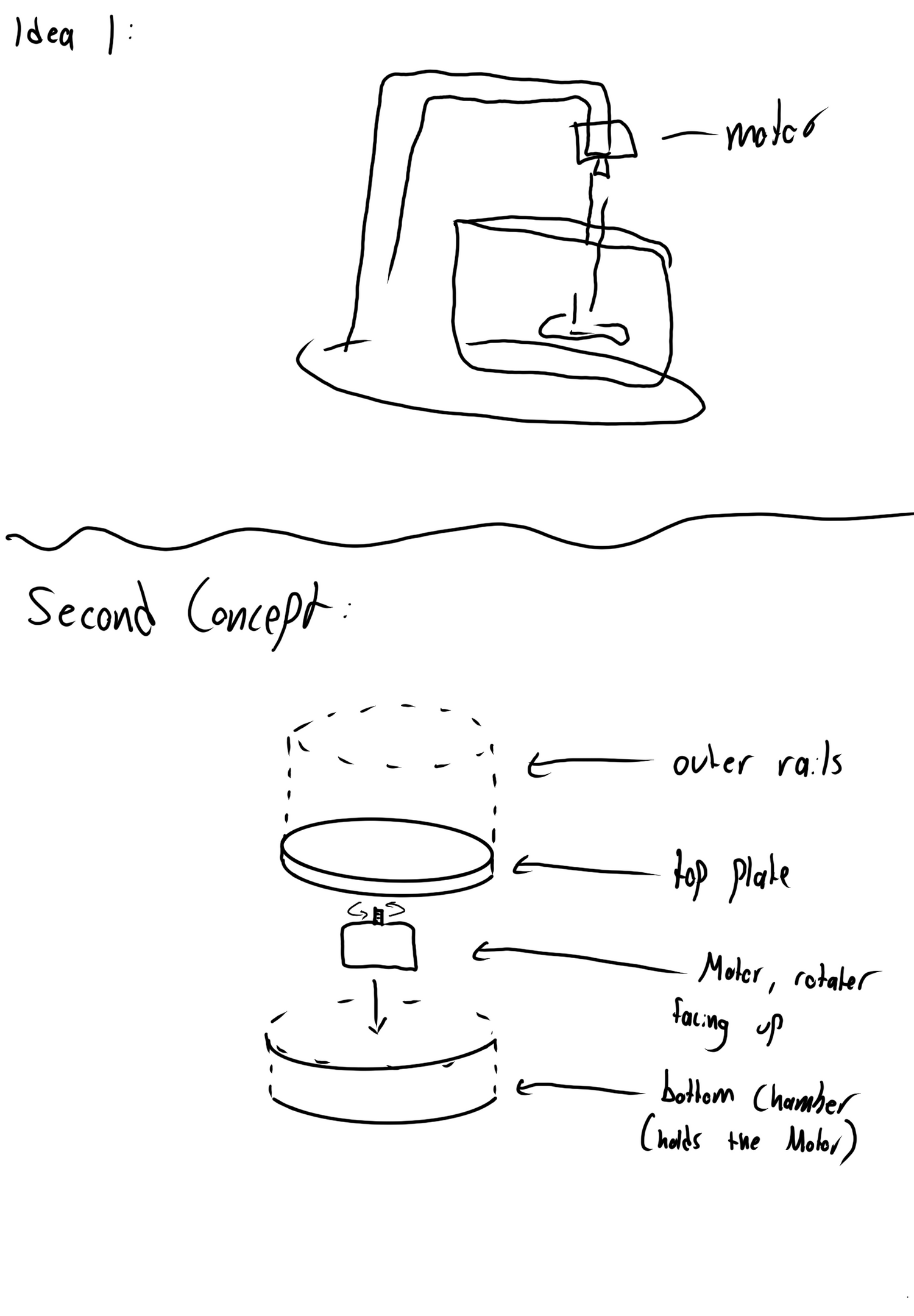
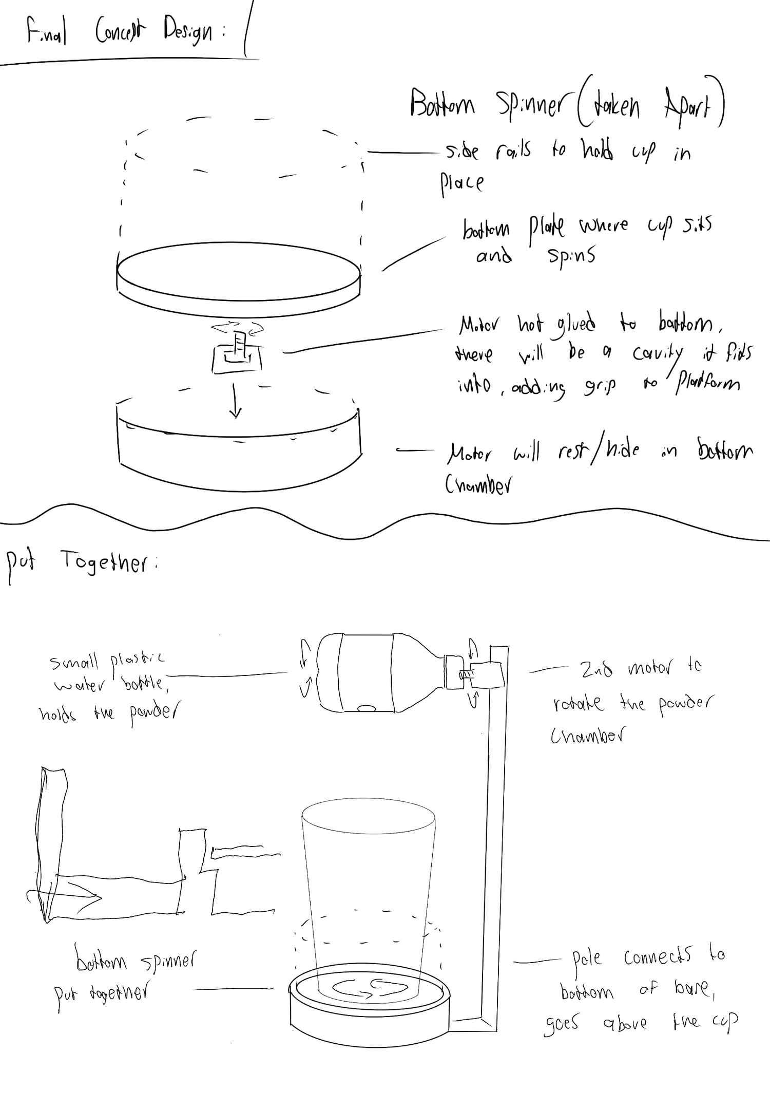
The first step in my process was sketching out every idea that came to mind. I focused on how I could get a motor to mix water effectively, but I was especially drawn to the idea of using a non-invasive mixing method. I found inspiration in a video of a drink mixer that spins the entire cup while keeping it secure with a border—simple, effective, and exactly the kind of mechanism I wanted to replicate.
I had a lot of creative vision for how the robot could look and behave, but I knew I needed to prioritize the functional requirements over the non-functional ones to make sure the project actually worked. I wanted it to be more than just a cool idea—I wanted it to reliably perform its task.
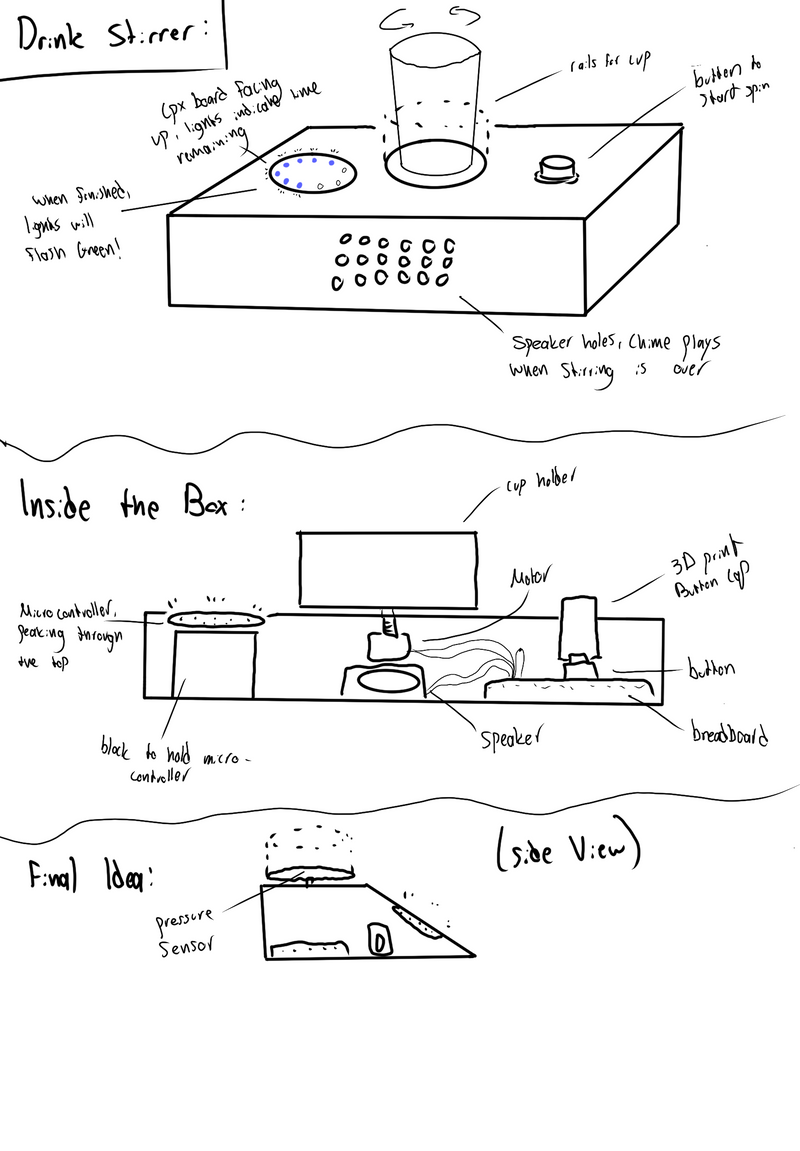
To make the concept more engaging, I started adding new features to the design. That's when I decided the robot shouldn't just mix the drink—it should also dispense the electrolyte powder. I sketched out different ways to make that work, laying the groundwork for a dual-function robot that felt both fun and functional.
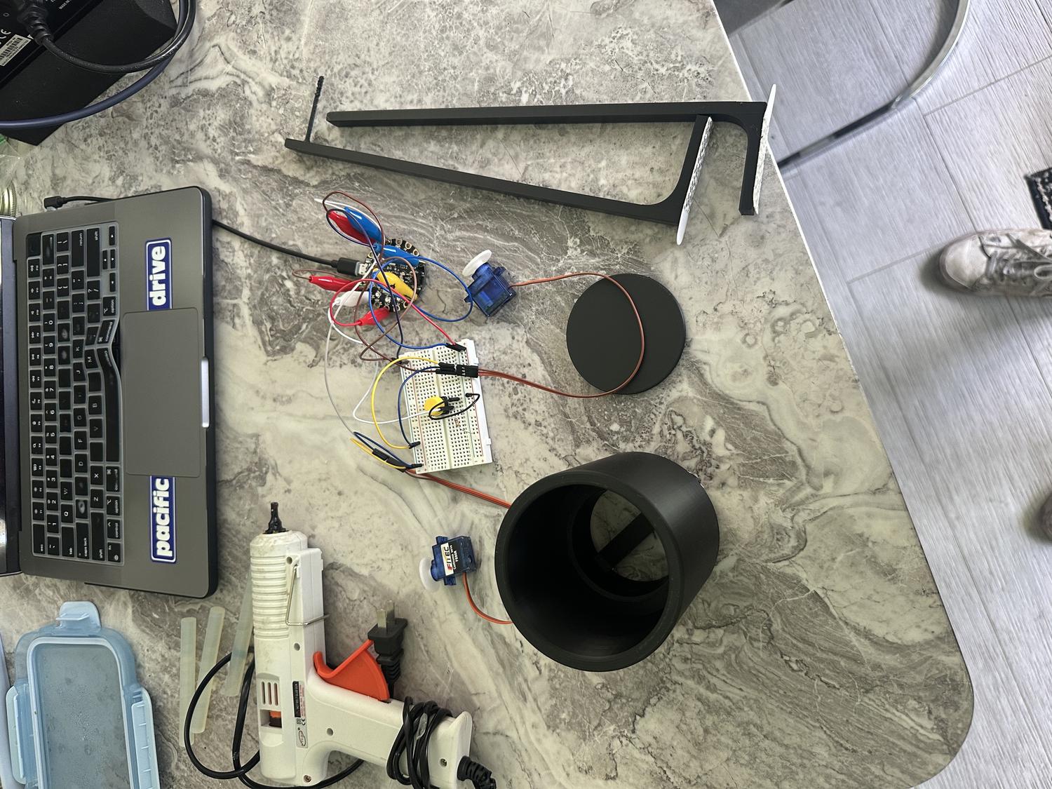
Planning The Build
Materials:
- 3D printed material (PLA)
- Hot glue
- Scotch tape
- Exacto knife
- Starbucks large cup
- Plastic ginger shot bottle
- Plastic Straw
- Digital caliper
- Circuit Playground Express board
- Alligator to male wires
- Male to male wires
- 2 servo motors
- Breadboard
- Button
First Step:
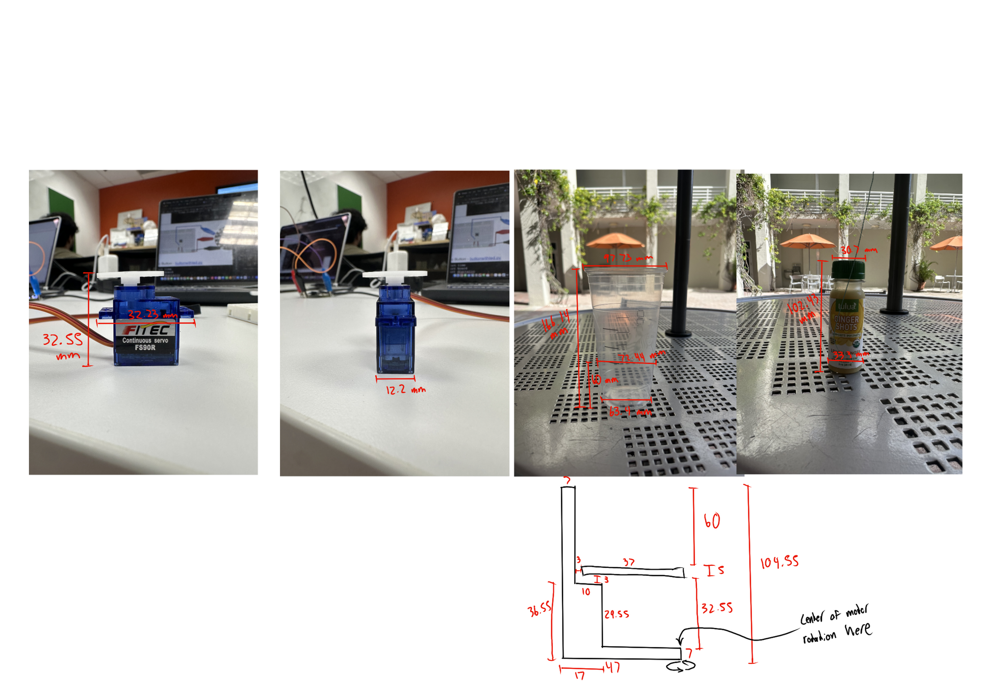
- Measured servos, cup, and bottle using digital caliper to inform 3D model dimensions
- Used OnShape software to begin 3D modeling the structure
- Built each part with precise measurements in mind to ensure proper fit and function
- Focused on stability, motor clearance, and how each part would interact when assembled
- Made a sketch that shows everything in the build, including the cup and bottle to ensure it would all fit on the first print
Next Steps:
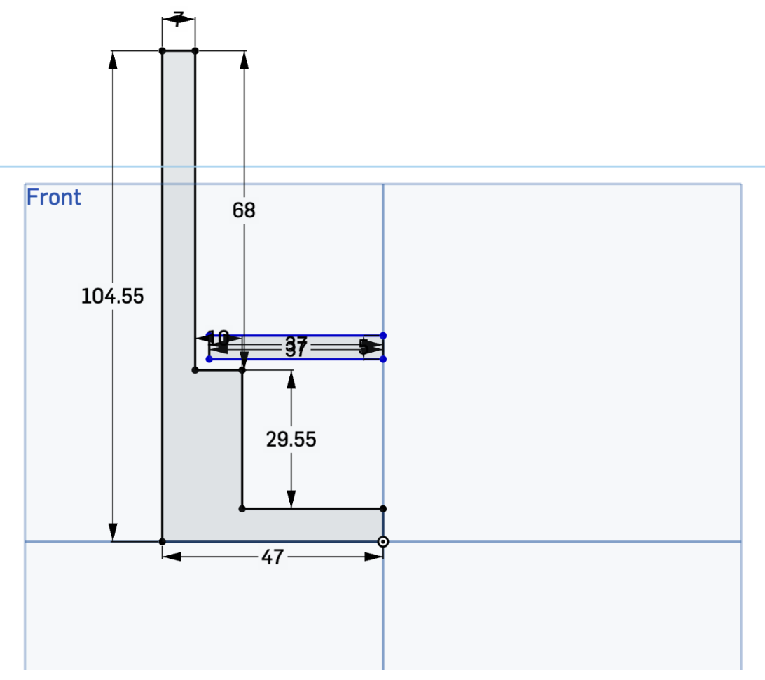
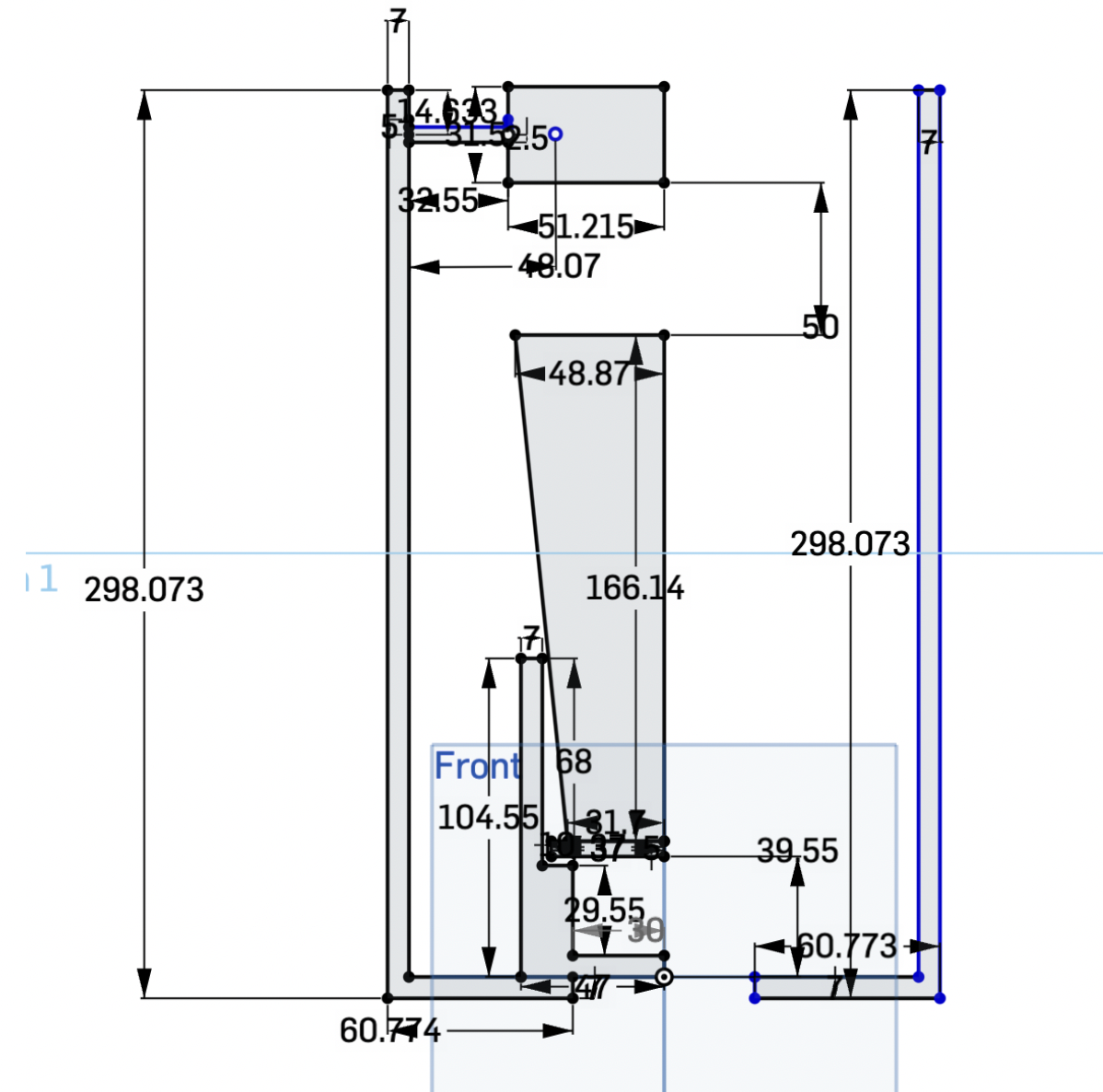
- Used revolve and extrude tools in OnShape to turn blueprint into a 3D model
- Created 3 separate files for different parts of the device
- Added 3mm of space between spinning plate and border to prevent friction and allow smooth movement
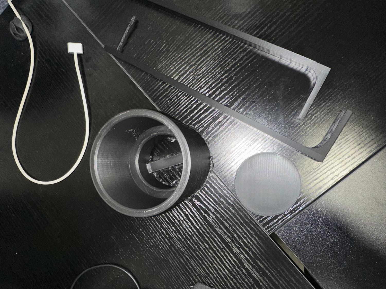
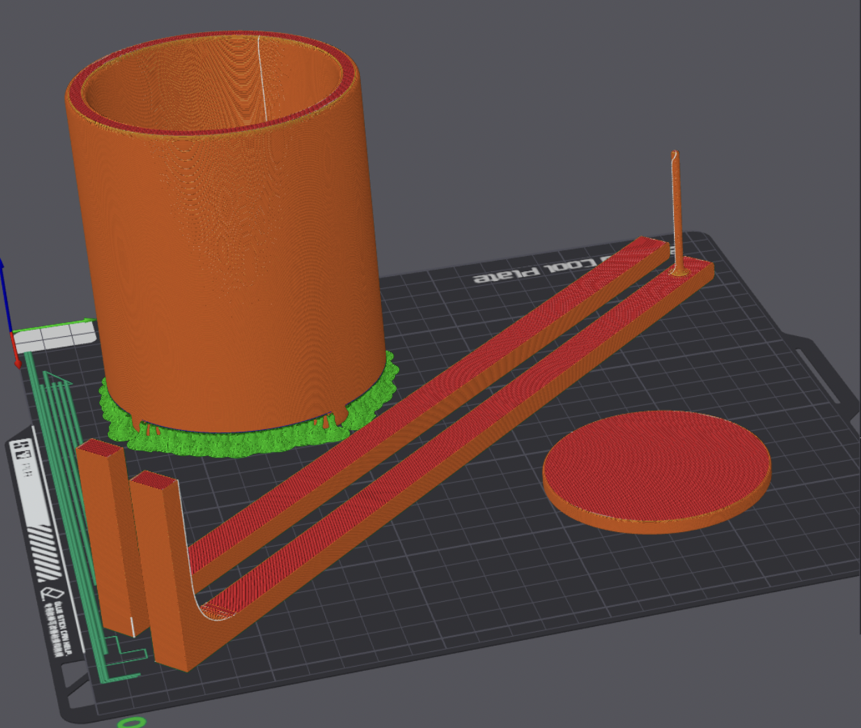
3D Modeling
- Exported the STL file and uploaded it to Bambu Studio for 3D printing
- Arranged all pieces to print in one take
- Added supports to the main compartment and spliced the file
- Exported the spliced file and began the printing process
Printing Process
- Print finished, moved on to wiring and programming servo motors
- Connected servos to Circuit Playground Express board and breadboard
- Set up process to run with a single button press
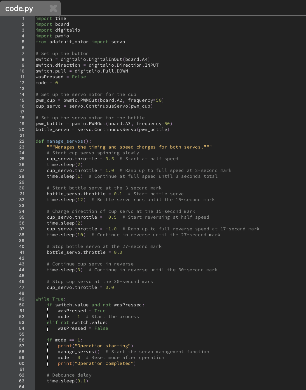
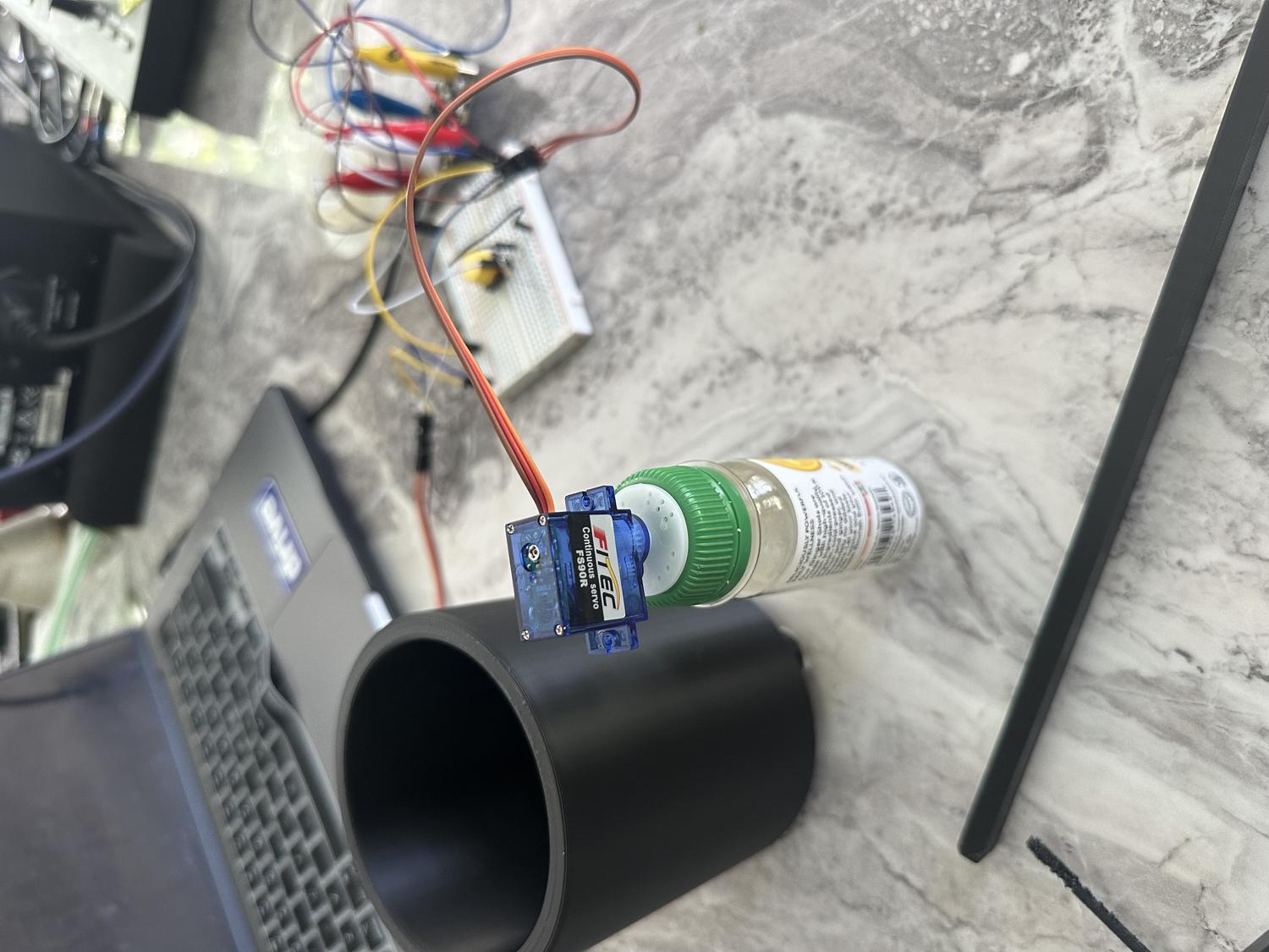
Wiring / Coding the Servos
Input:
- Button click
Output (2 outputs, 30 seconds total):
- Cup servo starts slow, then speeds up
- At 3 seconds, bottle servo starts spinning slowly to dispense powder
- At 15 seconds, cup servo reverses direction slowly, then speeds up
- At 27 seconds, bottle servo stops spinning
- At 30 seconds, cup servo stops and both servos are turned off
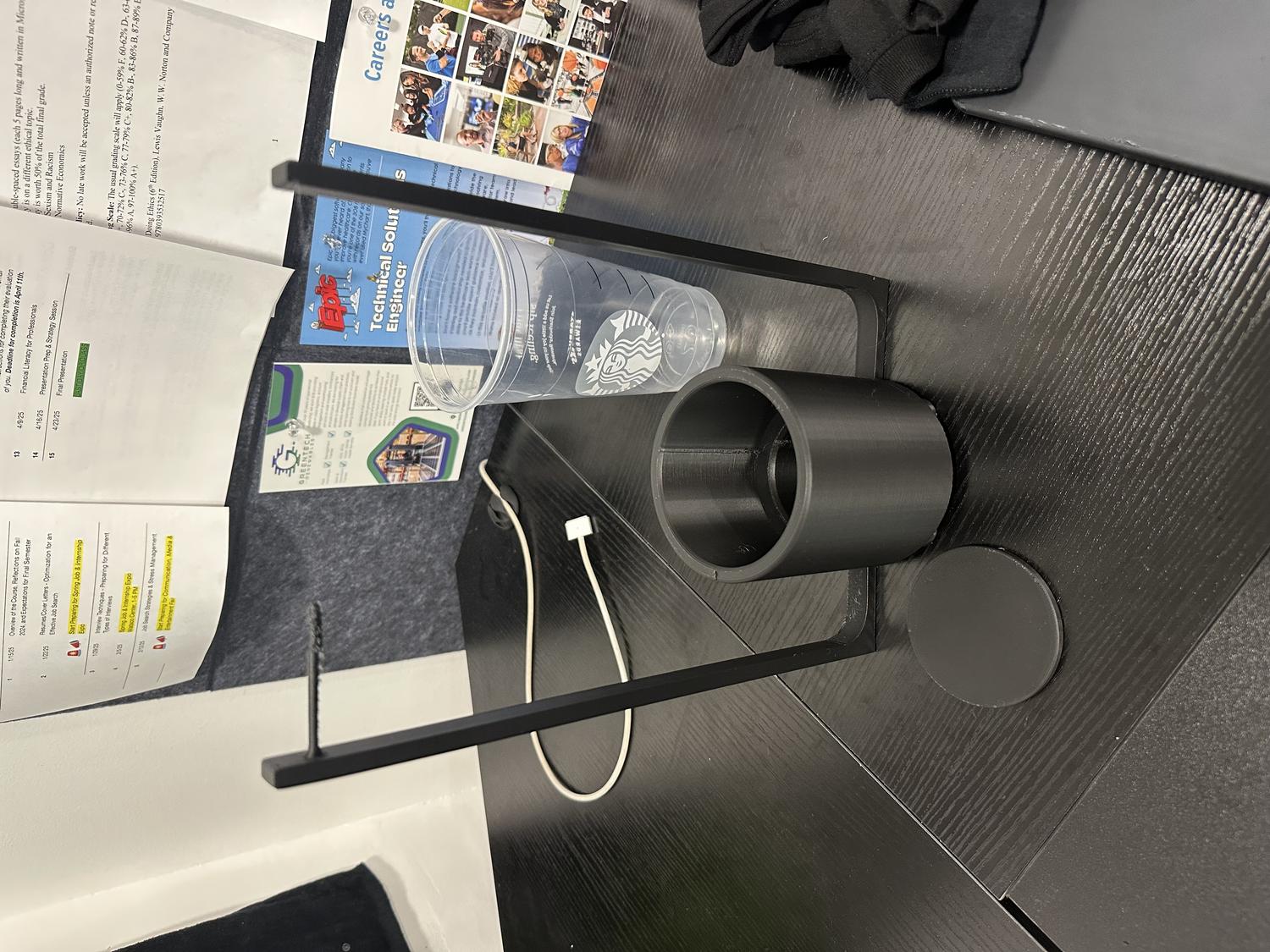
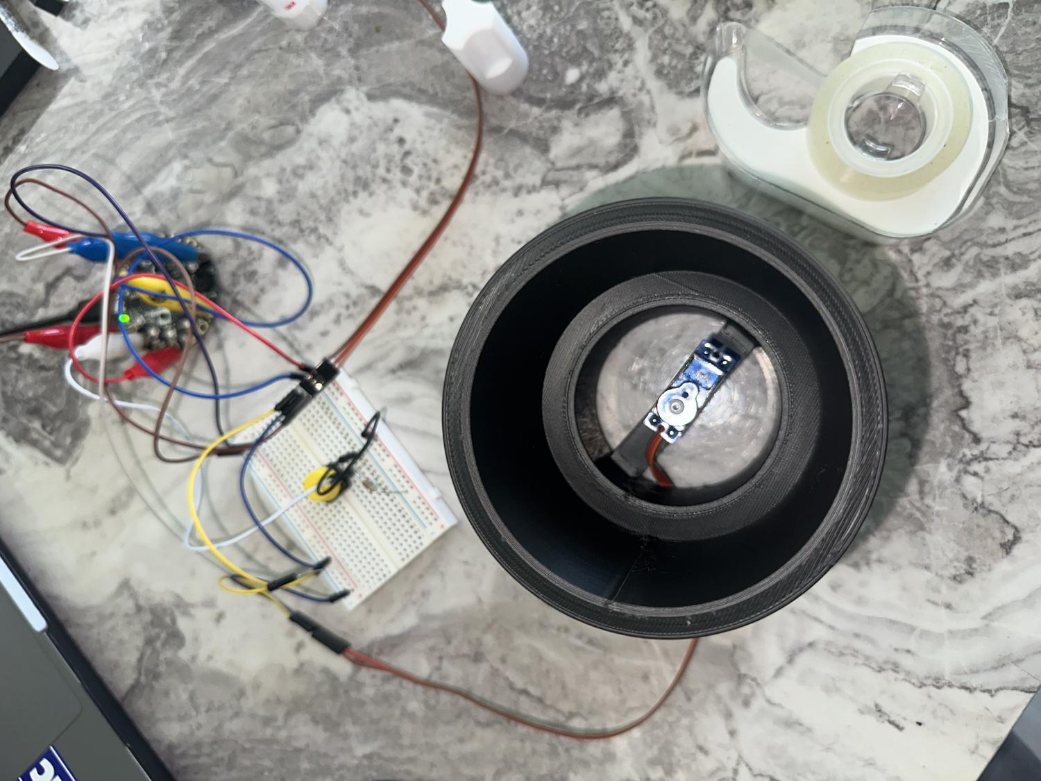
Assembly
- Built from servos: hot glued caps, cup servo to coaster, bottle servo to bottle cap; taped cup to bottom chamber, bottle to support frame
- Taped feet for stability; tested after each step
- Hot glued both frames to main compartment; straw from bottle into second frame holder
- Small incision in bottle for powder—revolves to dispense one scoop; bottle stays easy to refill and remove
- Full test run—everything worked
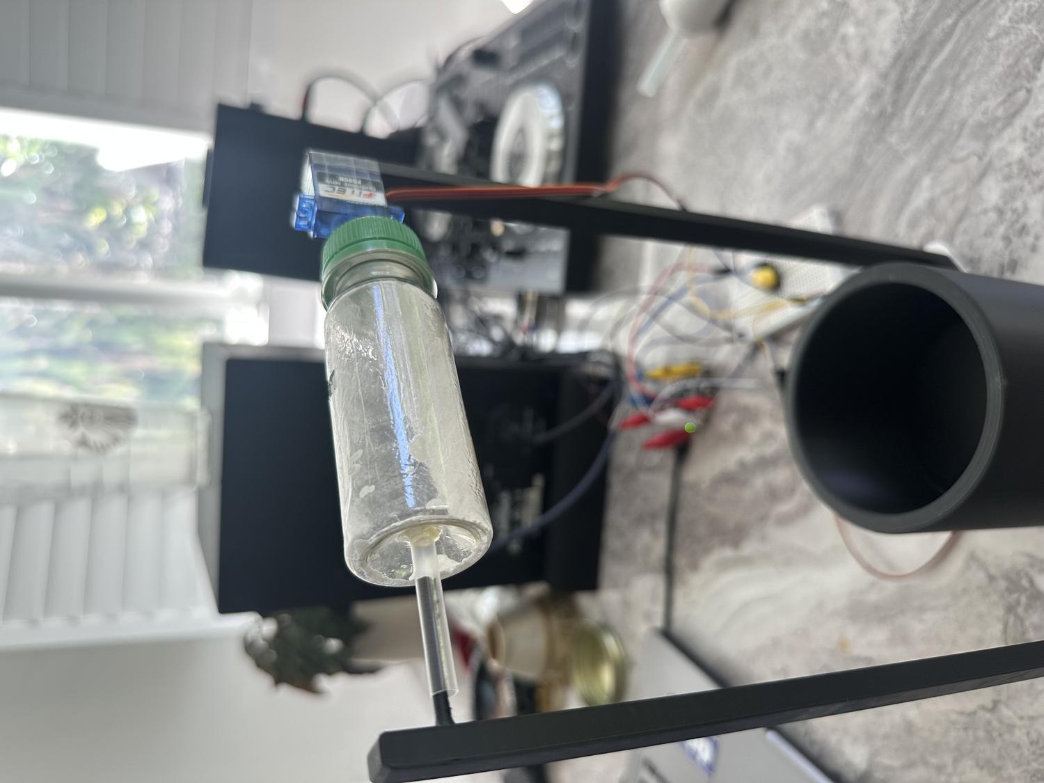
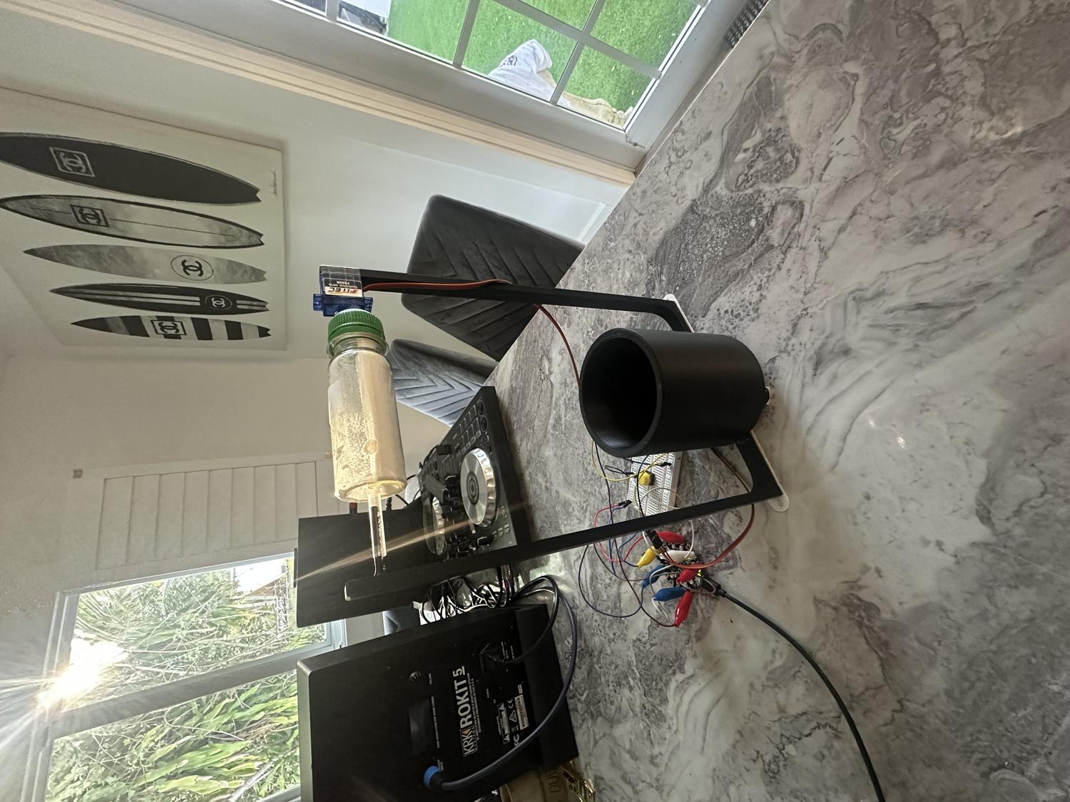
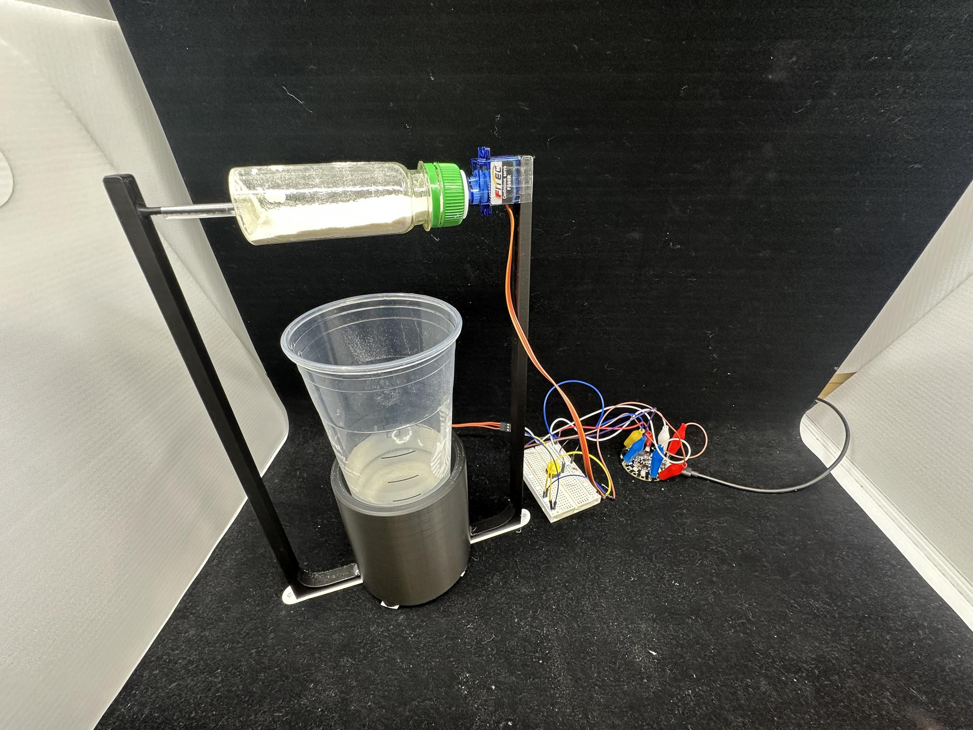
Finished Electrolyte Robot
Reflection
What Worked Well:
- Overall design is stable, nothing breaks or feels out of place
- Powder can be easily added, and the bottle is easy to remove and replace
- Servos are sturdy and stay in place with no malfunctions
Challenges & Limitations:
- Servo motors have limited power and can only reach a certain speed
- Mixing effect isn't strong enough to fully stir the water as intended
- Hole in the bottle could finish rotation upside down, releasing powder when turned off
Takeaways:
- The goal was to build a device that may or may not be a helpful robot
- In this case, it's not extremely helpful due to limited servo speed
- Future versions could include faster, more powerful motors
- Despite limitations, this was a successful first prototype that met the core design goals
Revolve Underground LED Sign
For my first project in Physical Computing of Spring 2025, the task was to create a diorama that expresses something personal about myself, using a combination of paper, a vinyl cutter, and programmable electronics. I drew inspiration from a personal venture that began in January 2025 when a few friends and I started a record label in San Diego and branded it as "Revolve Records". Our goal was to boost the deep/tech house music scene and discover creative methods to promote and brand our label. Creating a dynamic, LED-lit sign seemed like the perfect blend of technology and expression to spotlight Revolve.
Getting Started
The initial step was to lay out all my creative thoughts and conceptualize the design visually. This process began with jotting down every idea that came to mind and then translating these concepts into basic sketches. These sketches served as the foundational blueprints that shaped the project's direction.
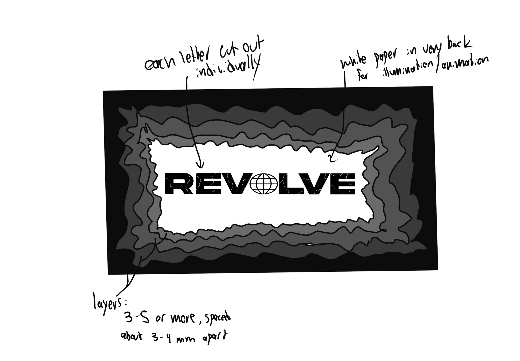
The design needed to be unique, incorporating multiple layers to add depth. I imagined utilizing sheets of black paper, each featuring crater-like cutouts with spaces between them, which added layers of texture to the design. Central to the design was a panel of RGB LEDs, which would backlight the 'Revolve' letters to create a silhouette effect, mimicking the pulse of house music. Allow me to guide you through my thought process and how I brought everything together.
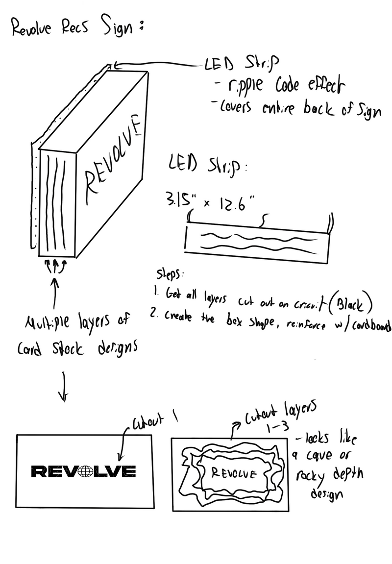
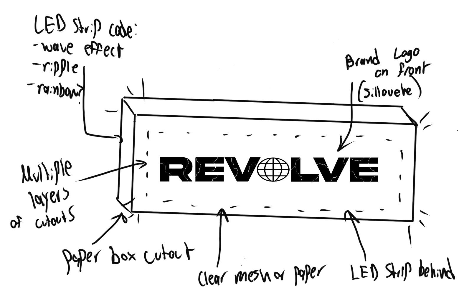
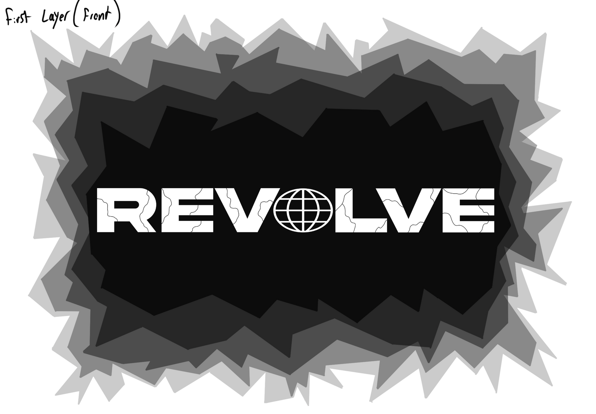
- Used Procreate on iPad to design the sign's front with a chipped/broken asphalt motif
- Symbolizes the breakthrough of the underground music scene
- Initial designs set aesthetic and functional parameters for the project
- Converted design layers and logo into PNG files for Cricut Design Space
Test Print
- Shrunk cutout PNGs in Cricut Design Space for better margins of 1.5–2 inches between layers
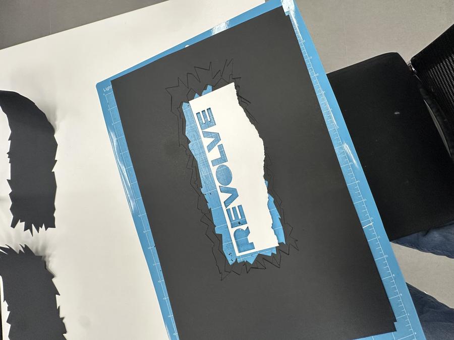
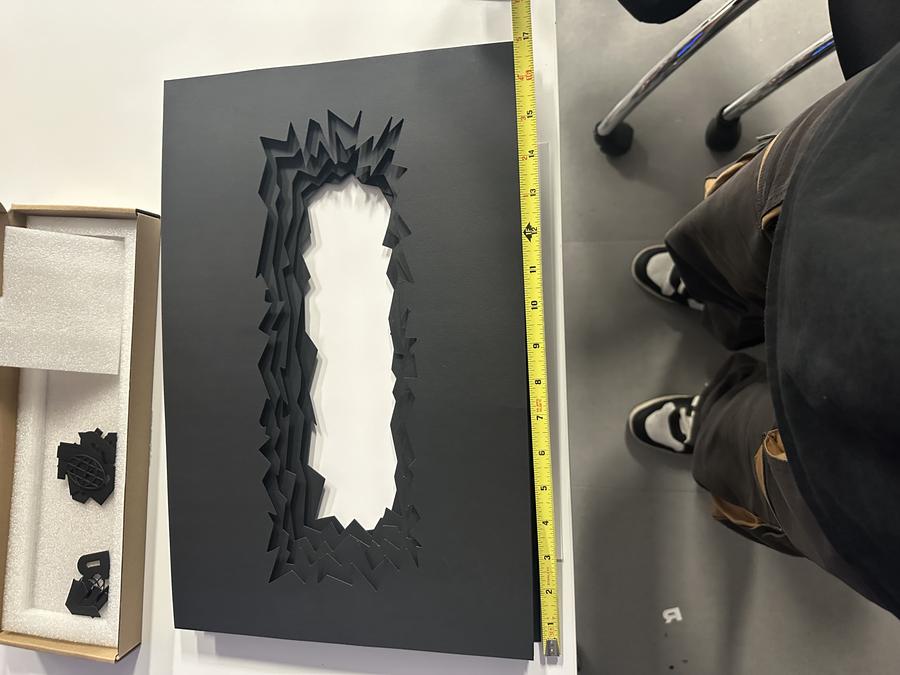
- Conducted test print with 11×17 inch black cardstock and white printer paper to assess Cricut Maker 3 vinyl cutter use
- Test print determined optimal sizing and placement of cutouts to match design vision and equipment capabilities
- Checked material sufficiency for holding the design together
- Satisfied with test results, proceeded to refine and perfect the design
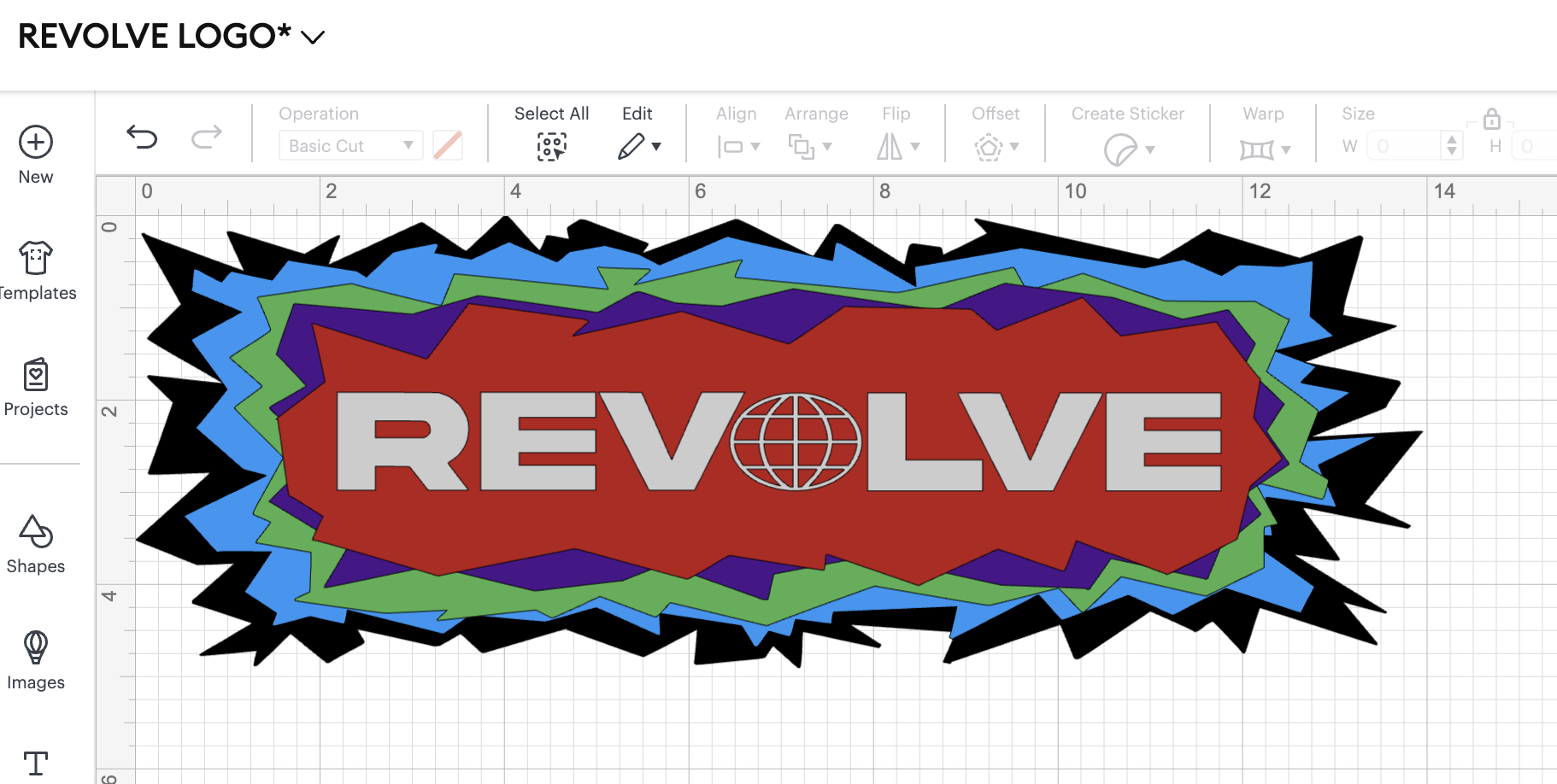
- Adjusted sizing and placement of crater cutouts and refined 'REVOLVE' logo dimensions after test print feedback
- Enlarged the smallest opening in the cutout, especially the 5th layer, for better LED panel illumination
- Reconfigured PNG cutout sizes to fit LED panel and securely encase 'REVOLVE' letters
- Enlarged the logo, particularly the globe symbol, to enhance the cutting process and scaled up the entire design for uniformity
- Final mockup measured about 4.3 inches × 14 inches, perfectly centered on the 11×17 inch black cardstock paper
Final Print
With these adjustments, I finalized the layout and was ready to move forward. This preparation set the stage for crafting the final version of the project, requiring careful planning and organization of the materials needed for completion.
Materials:
- 11×17 inch Black Cardstock (80 lbs)
- White Cardstock (80 lbs)
- Styrofoam for spacers
- Black Spray Paint + Primer
- Velcro Strips
- Packaging Tape
- Gorilla Glue
- Elmer's Glue Stick
- Scissors
- Exacto Knife
- Tape Measure + Straight Edge
- Adafruit Circuit Playground Express Board
- 3 connective wires (GND, Power, and A2)
- USB cord
- RGB LED Panel (WS2812B, 256 neopixels)
- Cricut Design Space Software – Exact Print Details
First Step:
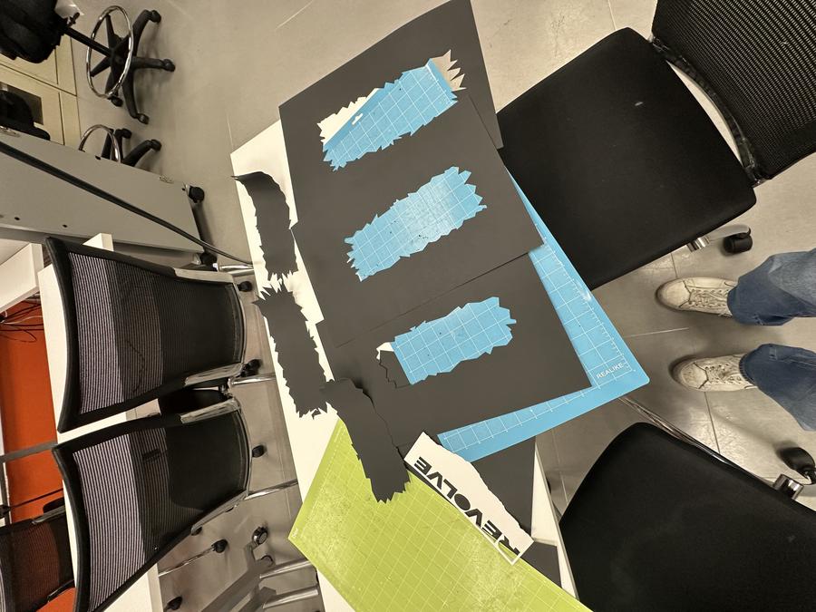
- Completed final prints with vinyl cutter, ensuring precise centering on 11×17 inch black cardstock
- Successful print of five paper sheets and cleaner 'REVOLVE' letters due to size adjustments
- Measured front frame; total thickness of stacked frames was 1.25 inches
- Recorded dimensions critical for designing supportive frame
- Careful planning and execution vital for assembling final project version
Coding the RGB Panel
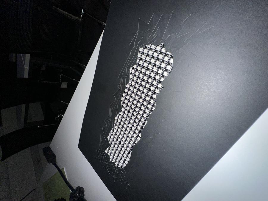
- Finalized main design and tested LED panel illumination through cutouts
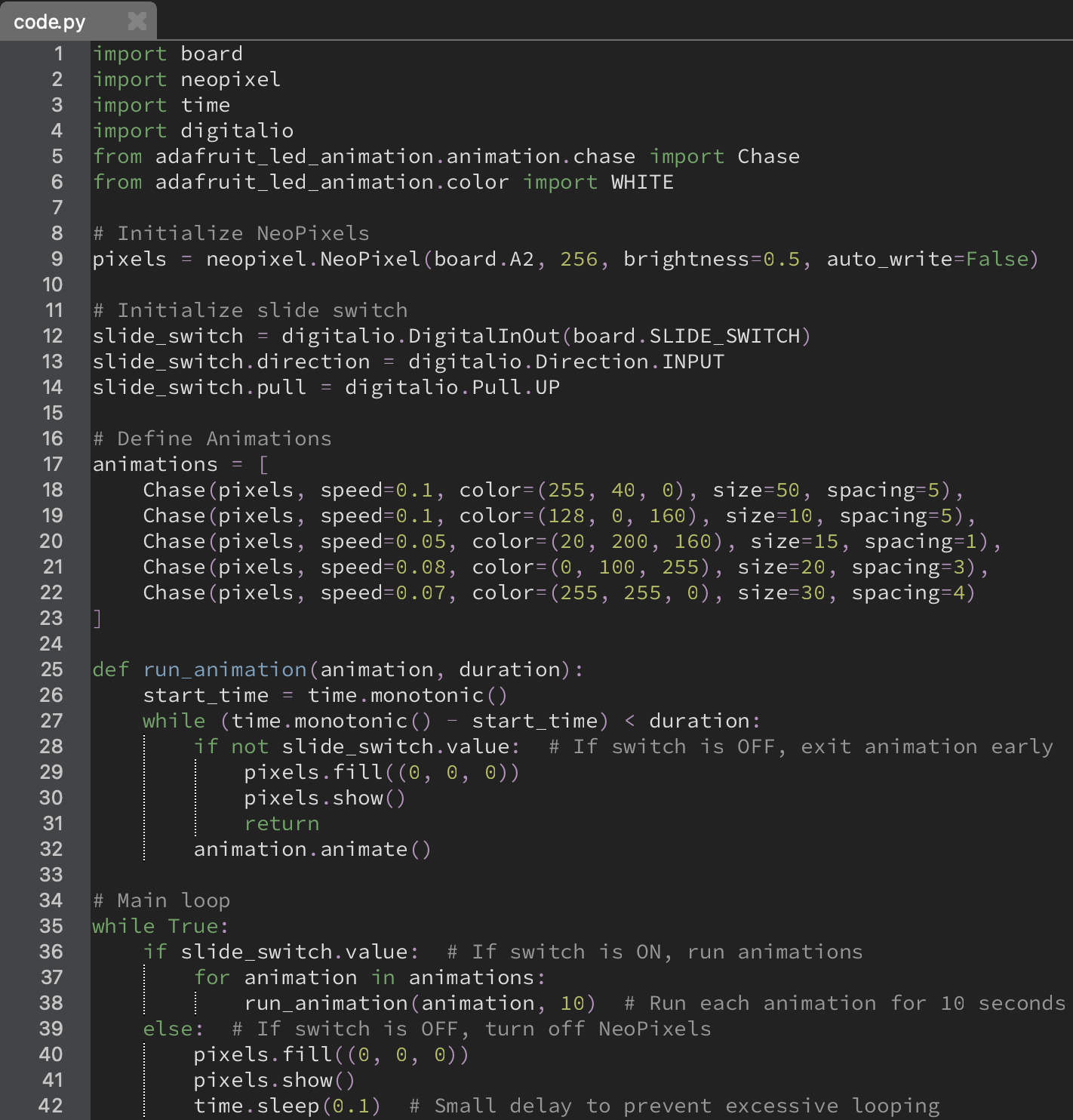
- Programmed LED panel for a dynamic "chase" effect, mimicking movement
- Adapted NeoPixel sequence code to match vision, setting specific colors and speeds
- Programmed LEDs to highlight 'REVOLVE' letters and enhance design aesthetic
- Configured sign with 5 movement patterns and colors, alternating every 10 seconds
- Added input-output code for simple on-off switch functionality on the circuit board
5V → VOUT
GND → GND
DIN → A2
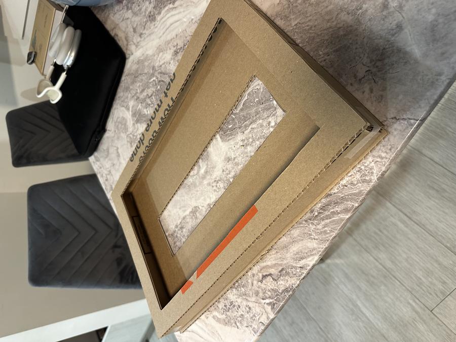
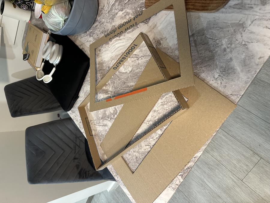
Creating the Frame
- Cutouts, logo, and LED programming completed, started building the cardboard frame for stability and ease of cutting
- Designed a simple shell frame with a front and back cover to secure all pieces in place
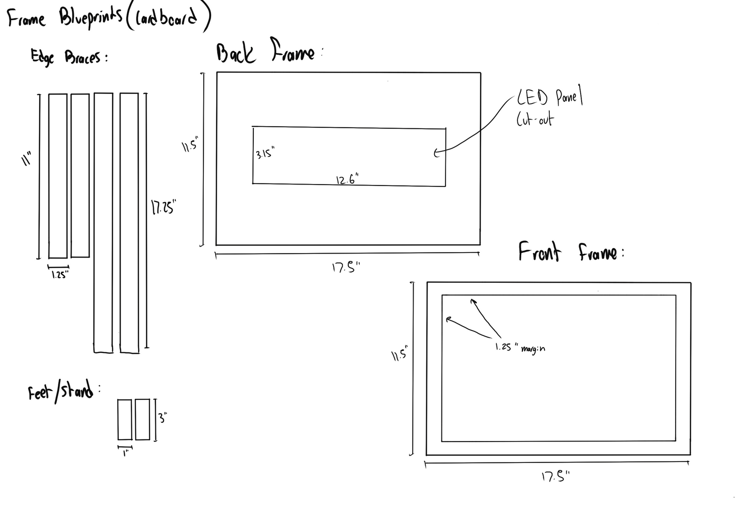
- Measured total dimensions for stacked cutouts at 17×11×12.25 inches and drafted initial frame designs
- Sketched blueprint focusing on frame dimensions and connection points
- Adjusted frame dimensions for better fit and added support: increased length to 17.25 inches for stability
- Extended front and back frame by a half-inch for assembly tolerance
- Incorporated an opening in the back frame for LED panel visibility and a 1.25-inch margin in the front frame
- Drew up frame design and visited Home Depot for supplies
- Purchased cardboard, an exacto knife, and spray paint for finishing
- Transferred blueprint from iPad to cardboard at home
- Began cutting out frame pieces
Assembly
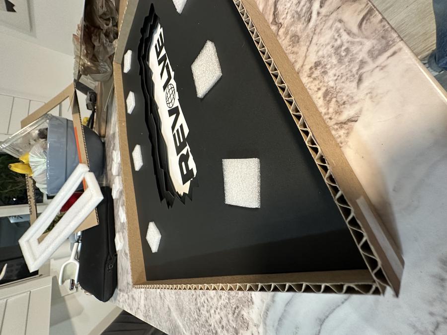
- Began careful gluing phase, crucial to avoid redoing printing and cutting
- Used glue stick for placing logo cutouts on white paper
- Checked fit by aligning cardboard perimeter frame around the cardstock
- Temporarily taped cardboard pieces to maintain alignment during gluing
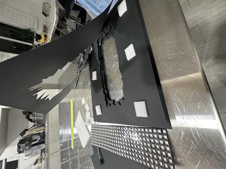
- Inserted eight 1×1 inch styrofoam pieces, 4 mm thick, between layers for even spacing and added depth
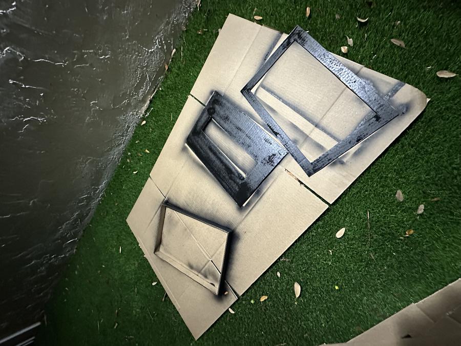
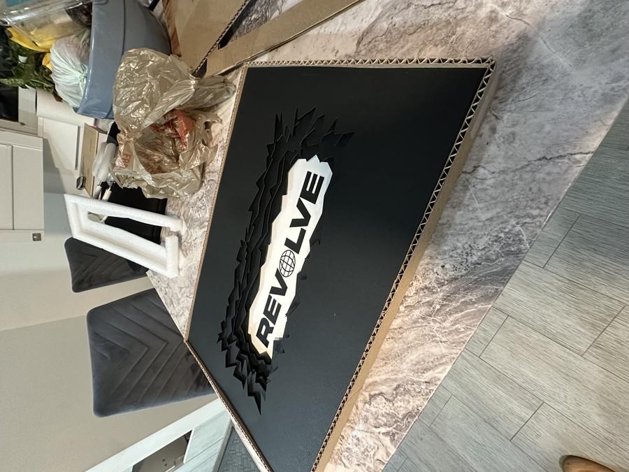
- Spray painted all pieces then began assembling cardboard frames
- Applied superglue along edges for a strong bond and added stiffness
- Wrapped edges with packaging tape for extra support and a cleaner look
- Reinforcement gave the frame a more finished appearance
- Connected LED board using alligator clips to appropriate pins
- Secured wiring on the back with tape and velcro for organization and easy removal
- Attached little feet cutouts to the frame's bottom, completing assembly
- Designed the piece to be lightweight for wall hanging, enhancing display flexibility
Input:
- Switch flip on Circuit Board
Output:
- RGB Panel Code Begins
- Every 10 seconds, the mode switches
- 5 different light effects and colors
Light Modes
Plant Health Monitor Project
Problem Statement:
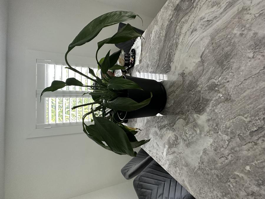
While being preoccupied with schoolwork or other activities, my housemates and I have a hard time remembering to water the indoor plants due to lack of attention and a reliable reminder system that can seamlessly integrate into our daily routines. I need a product that provides a subtle and effective reminder for busy housemates to water our plants utilizing a simple and unobtrusive solution to maintain their well-being and enhance our living space.
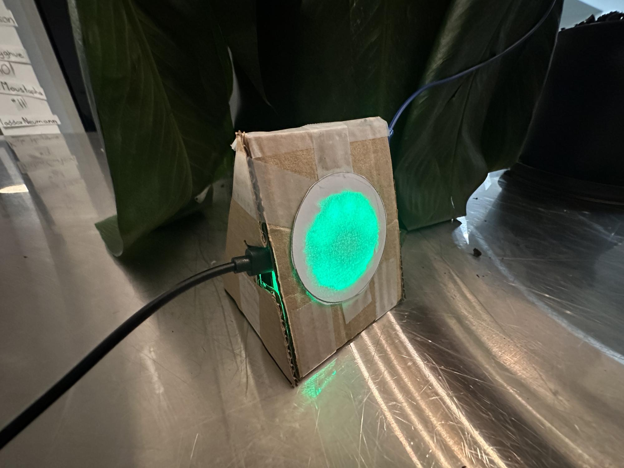
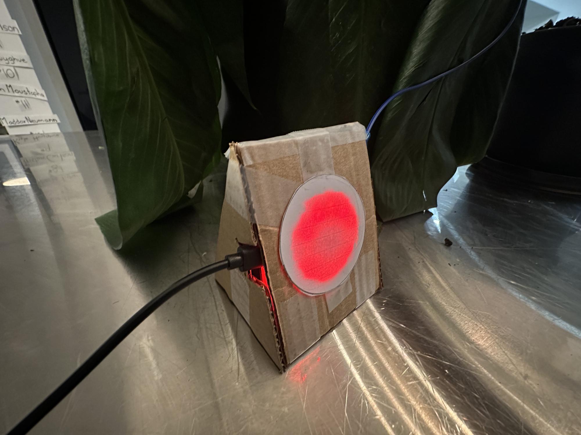
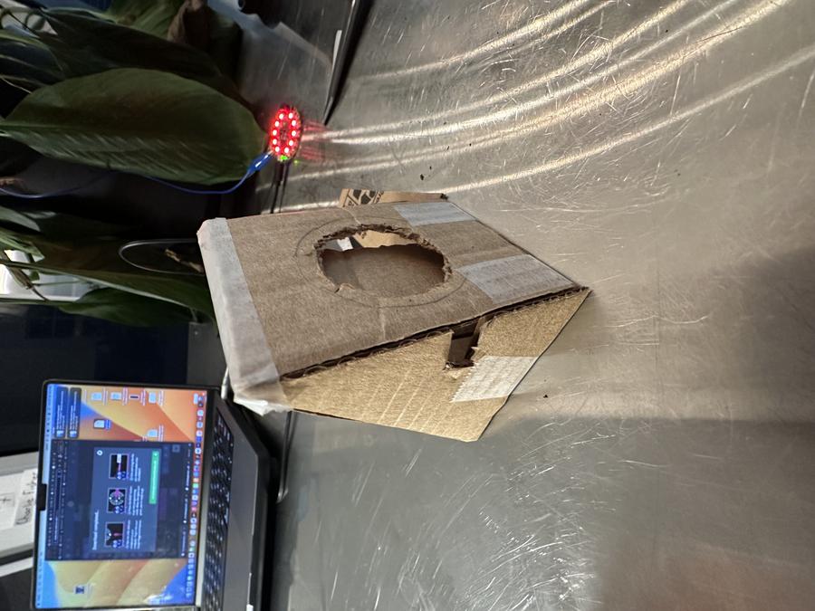
Solution:
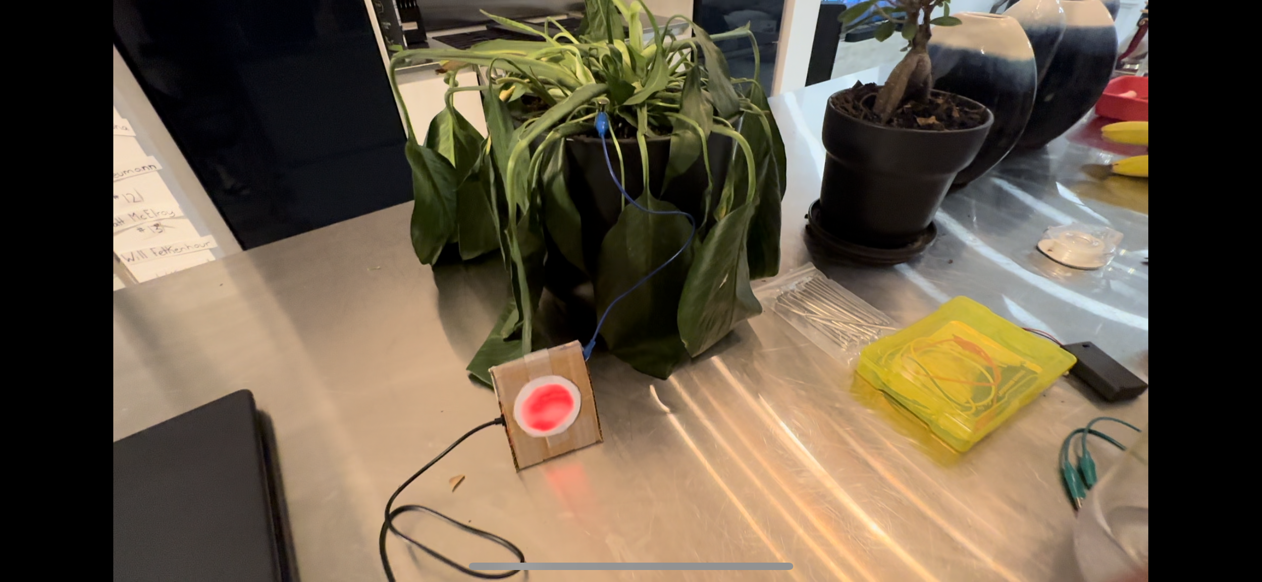
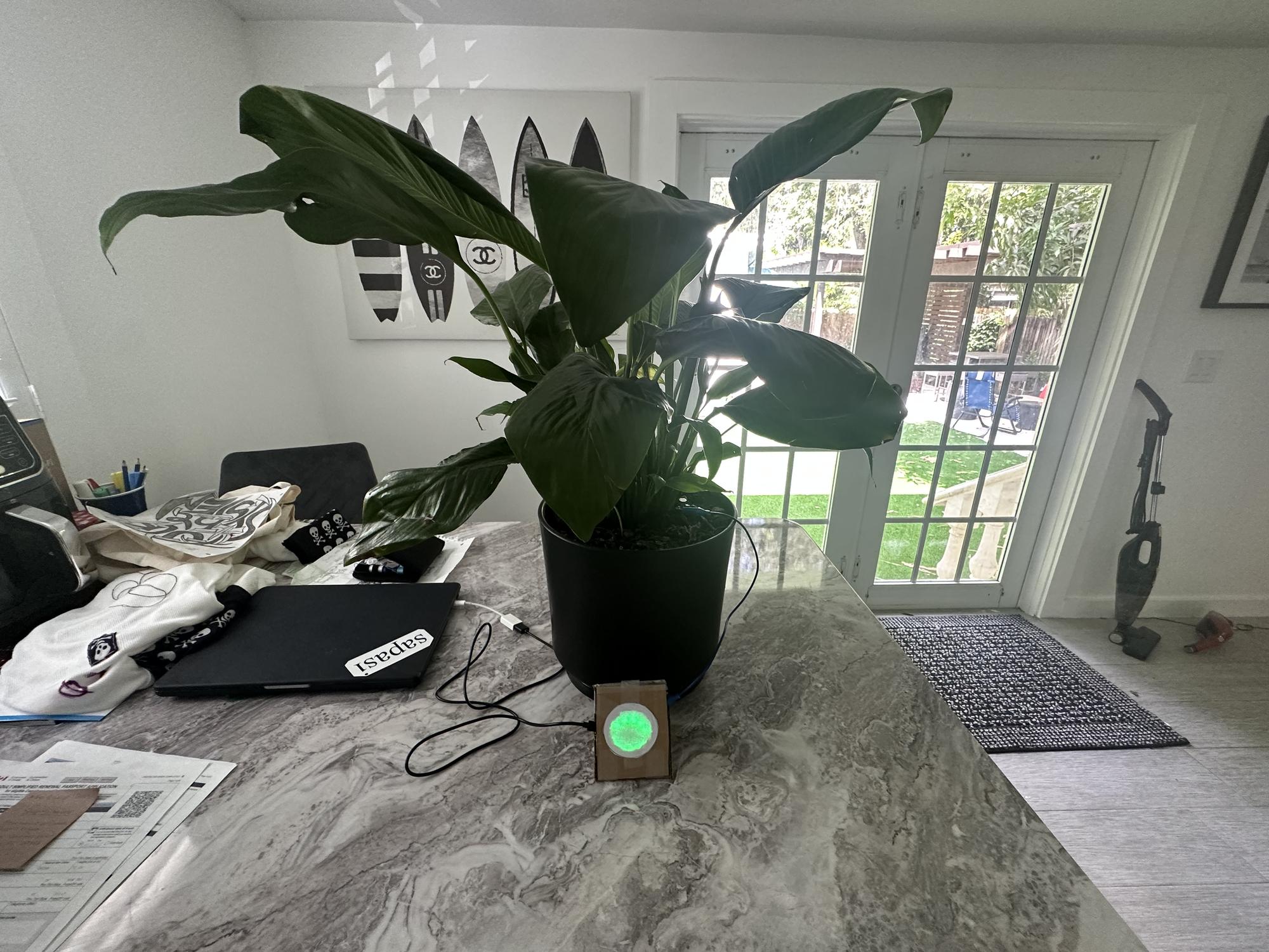
The Plant Health Monitor System is a device that utilizes capacitance technology to detect moisture in the soil of a plant. The device can subtly alert homeowners to water the plant since it has a light indicating its health status. The health monitor shows a green light for healthy soil, and red light for dry soil. Now, people in our house can easily get reminded of the state of our plants and we won't forget about them anymore.
Process
Materials:
- CPX Board
- USB cord / Battery pack
- Conductive Nail
- Alligator clip + wire
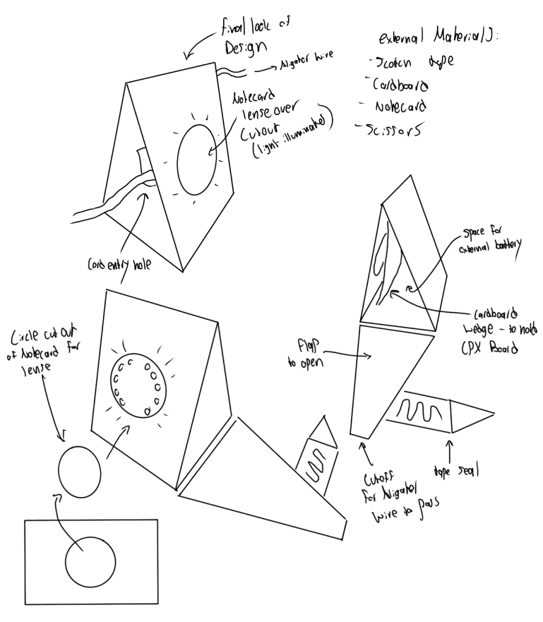
- Cardboard — for the structure
- Scotch tape — to hold it together
- Notecard — lens for the LED
- Scissors — make cuts
How it Works
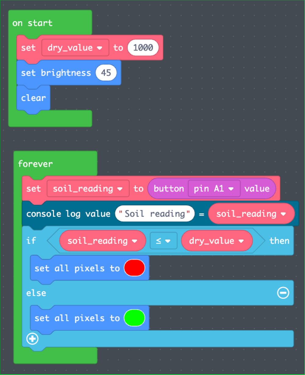
The CPX board can detect the capacitance (the ability to store an electric charge) on an analog pin (in this case, analog pin A1). As the moisture around a nail in the plant's pot increases, the value increases (we're creating a bigger capacitor). Dry soil doesn't work as well for electricity (like most dry materials except metals) so the value read by the CPX will be lower.
Since the nail is attached to an alligator clip, it is able to hold a current through it. The product reacts once any electrical conductivity (water) is detected, and the light will turn green when it senses it. When there is no more current, the light responds by turning red. There is only one input, and that is the reading from the A1 pin. There are no other inputs, such as buttons or movement signals. There are also only 2 outputs, green light and red light.
Results