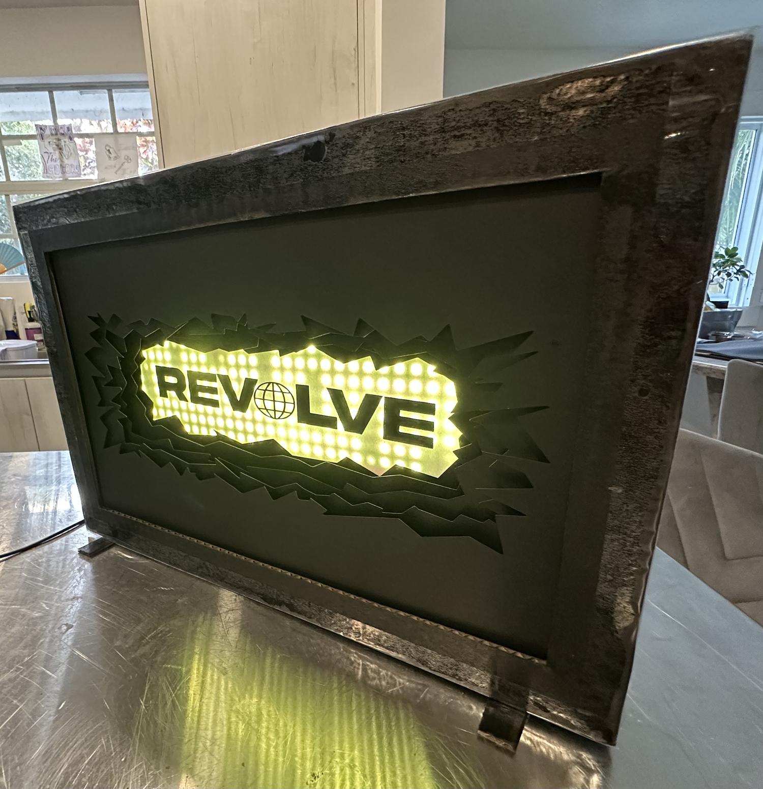
Remote-Controlled LED Desktop Lightbox (REVOLVE)
For my final project in Physical Computing of Spring 2025, I was tasked with either creating a new piece or refining a past project into a fully realized product. I chose to revisit my first project—an LED sign that spelled out "REVOLVE," the name of my record label. Rather than remake the sign entirely, I scaled it down to a desktop size that could be 3D printed in multiple parts and upgraded it to include a remote control sensor, eliminating the need to manually press the circuit board to turn it on.
Getting Started
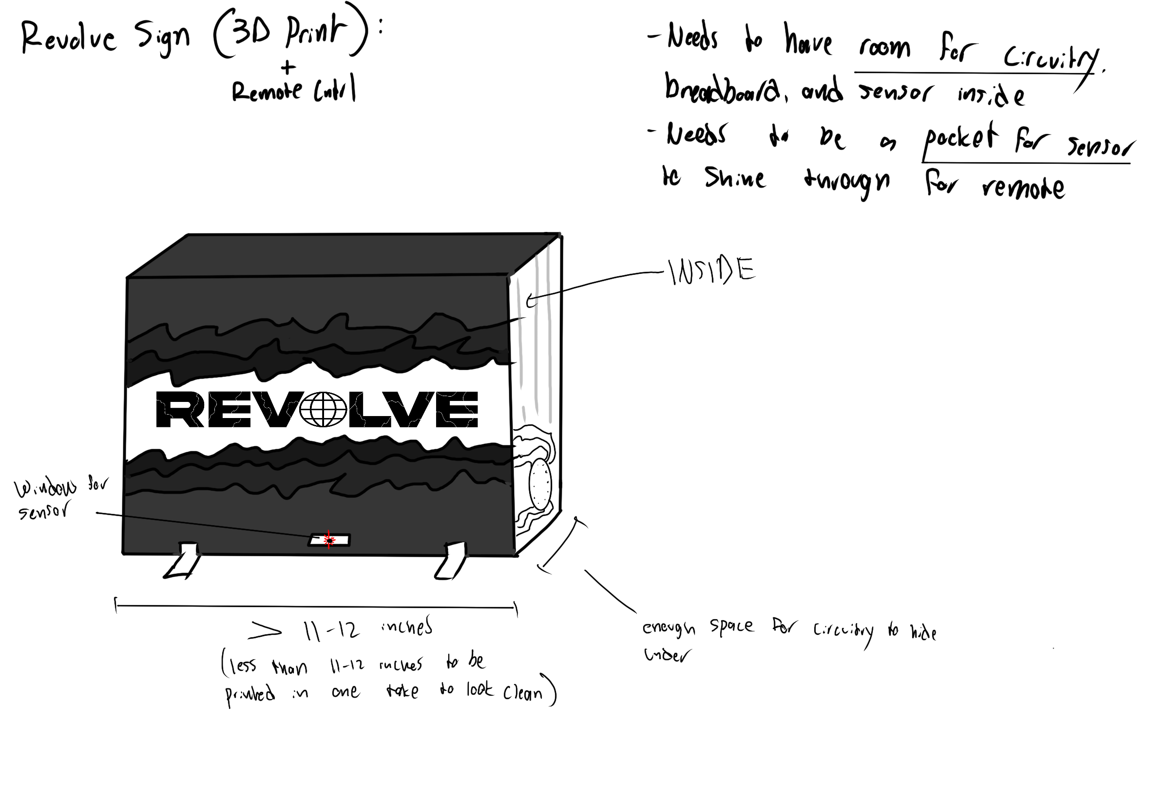
- Set design constraints based on 3D printer max dimensions (about 250mm width, depth, and height)
- Scaled down the original sign to fit within those limits
- Added a hole at the bottom so the infrared sensor could receive signals from the remote
- Made sure there was enough internal space to fit the circuit board and wiring
- No breadboard was needed—circuit worked with just the IR sensor and LED connections
Planning The Build
Materials:
- 3D printed material (PLA)
- Hot glue
- Black Duct Tape
- 8 x 1 mm Magnets
- Digital caliper
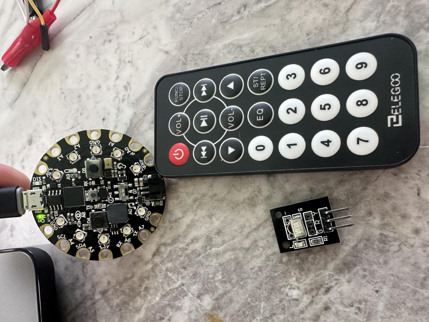
- Circuit Playground Express board
- Alligator to male wires
- Aligator to female wires
- 3X LED RGB Panels (8 x 8 Neopixels)
- IR Remote
- IR Remote Sensor
Steps:
- Measured each RGB panel - 80mm x 3 = 240mm
- Measured the circuit board - 50.7mm diameter
- Measured the IR sensor - 12.56mm tall
- Measured the sq ft of all wires together - 60mm x 65mm
3D Modeling
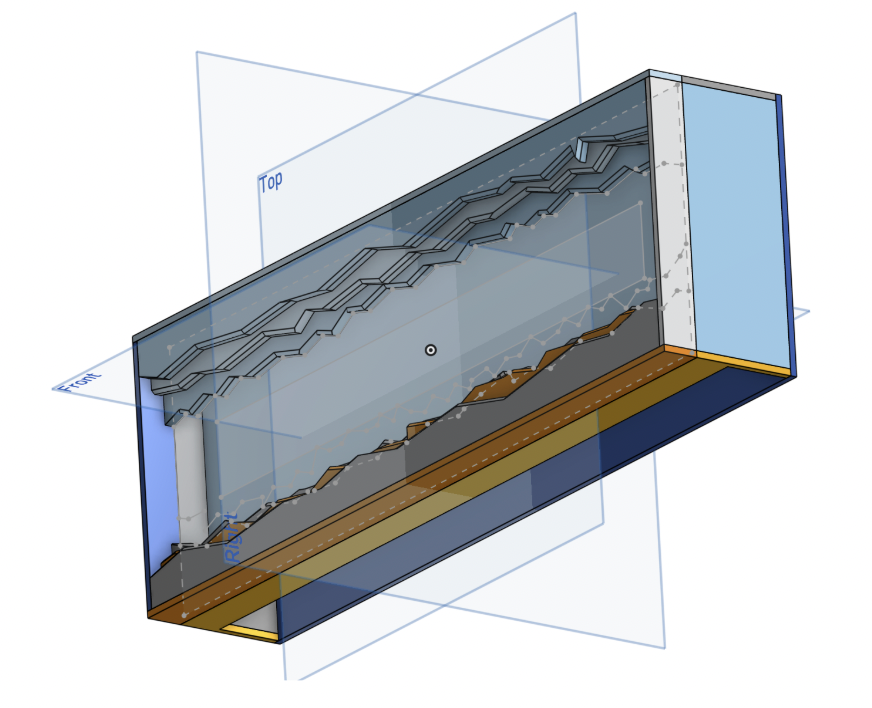
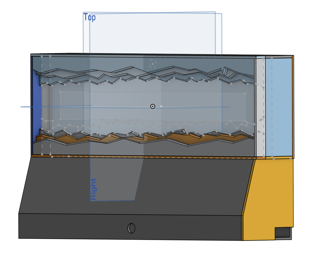
- Used Onshape to plan the build based on measured constraints
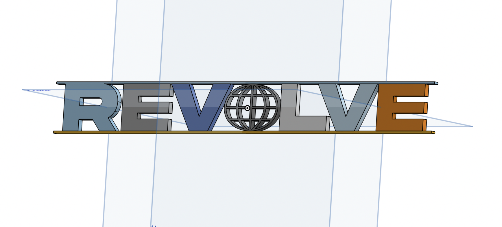
- Designed a front frame inspired by the original REVOLVE sign
- Created a clear frame for the LED light to shine through
- Added spacers to support and align internal components
- Modeled the back panel to hold all electronics securely
- Left a gap at the bottom for wire routing
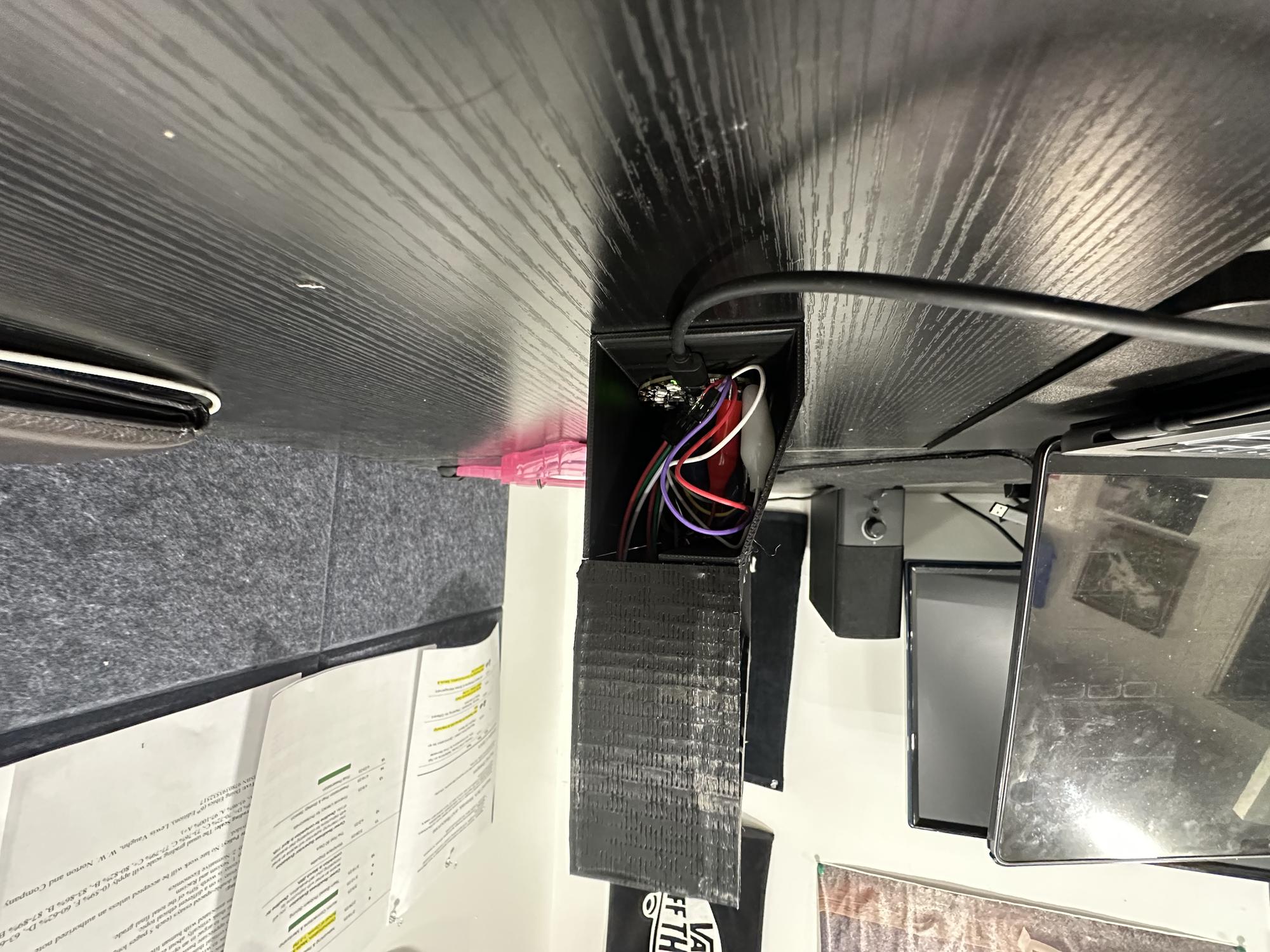
- Designed a bottom chamber to house the circuit board and sensor
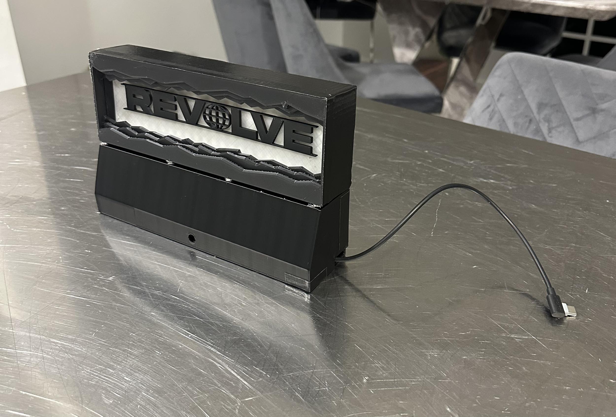
- Included a small hole for the sensor and another for the power cord exit
- Used the chamfer tool to make the "underground" cuts and grooves look more chipped and cracked
Printing Process
- Imported five separate pieces into Bambu Studio for printing: front frame, clear LED cover, back holder, bottom chamber, and chamber door
- Separated the parts to allow for proper assembly after printing
- Added supports to the main compartment and spliced the file
- Exported the spliced file and began the printing process
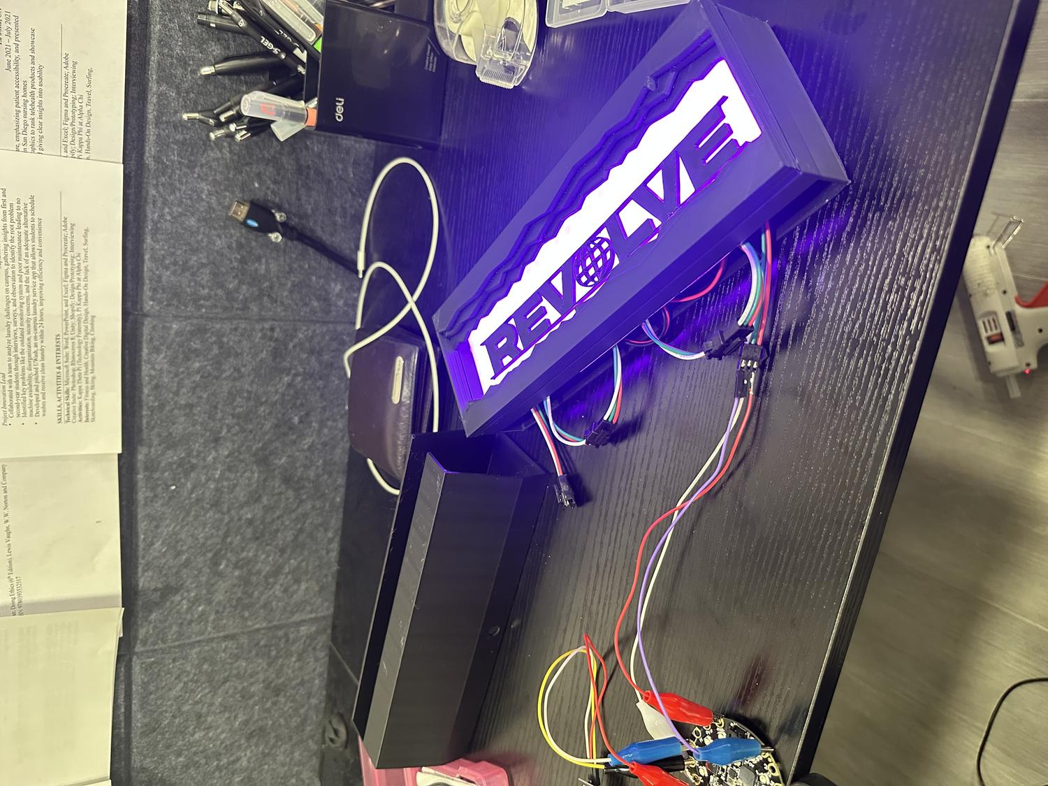
Wiring / Coding the LED Panel
IR Remote in Action
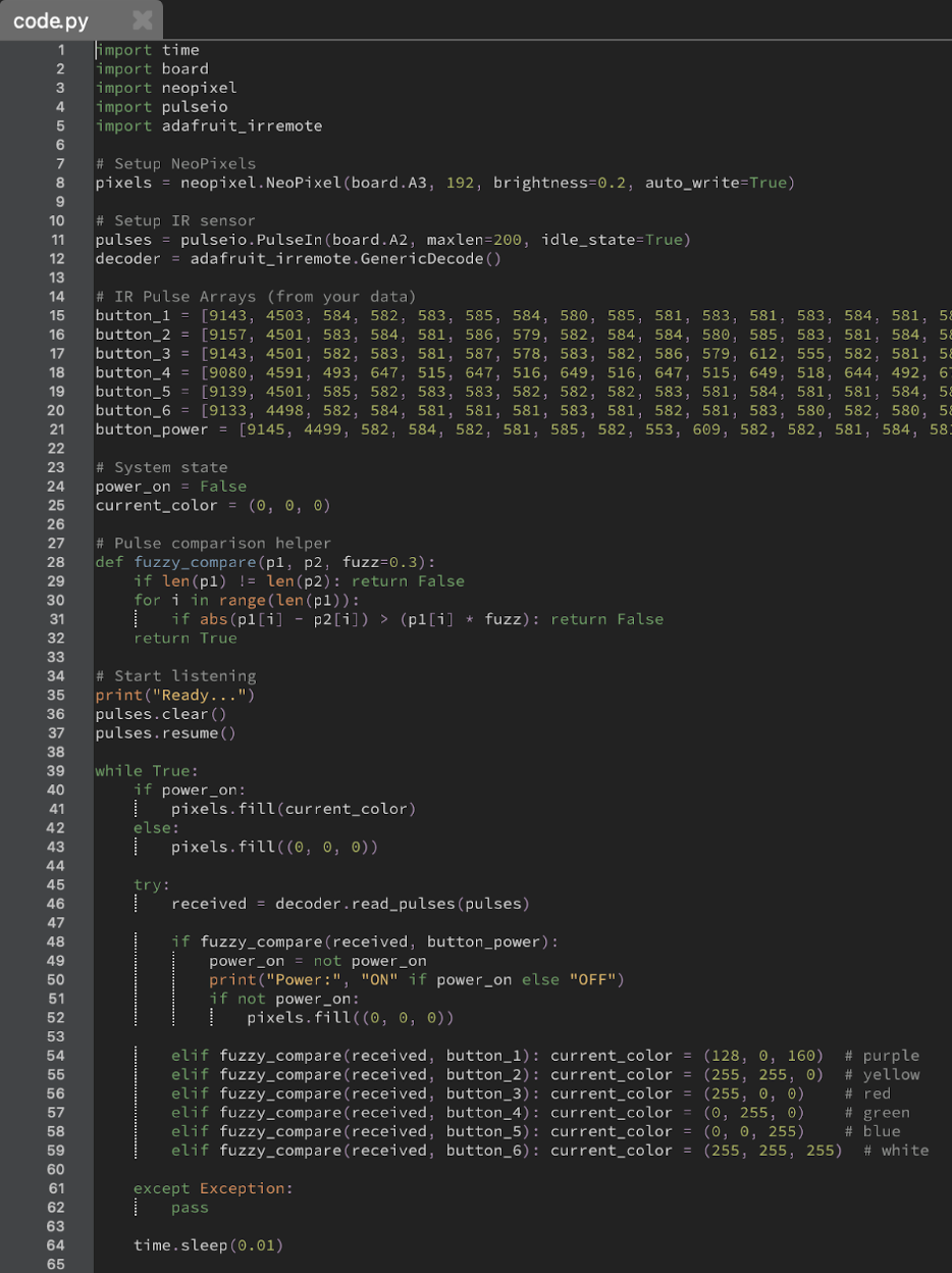
Python Code
- Used Mu Editor with a Python script to read IR remote pulse data via the terminal
- Collected pulse data for buttons 1–6 to assign six different colors to the panel
- Captured pulse data for the power button to toggle the device on and off
- Planned to include more features like LED chase effects, brightness control, and extra colors
- Limited RAM on the board (due to 192 NeoPixels) restricted how much functionality could be added
Inputs / Outputs:
| Inputs | Outputs |
|---|---|
| Power Button | Turns device on or off |
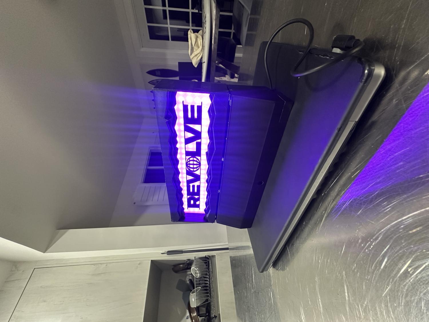
| Button 1 | Makes neopixels purple |
| Button 2 | Yellow |
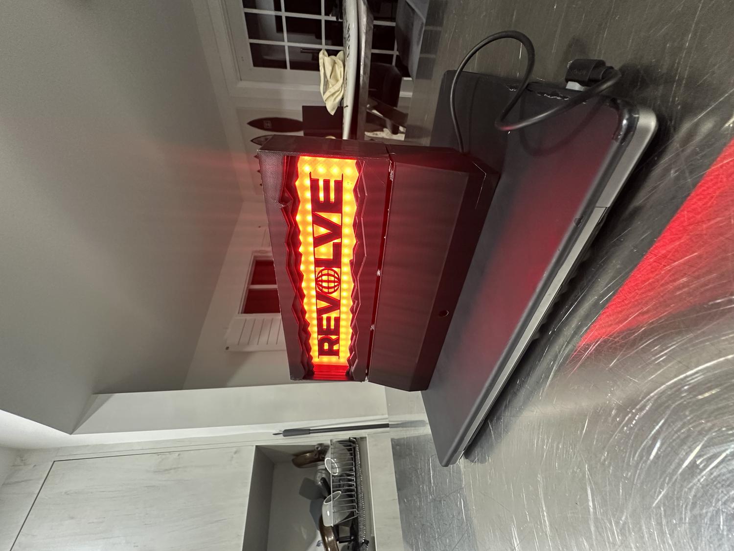
| Button 3 | Red |
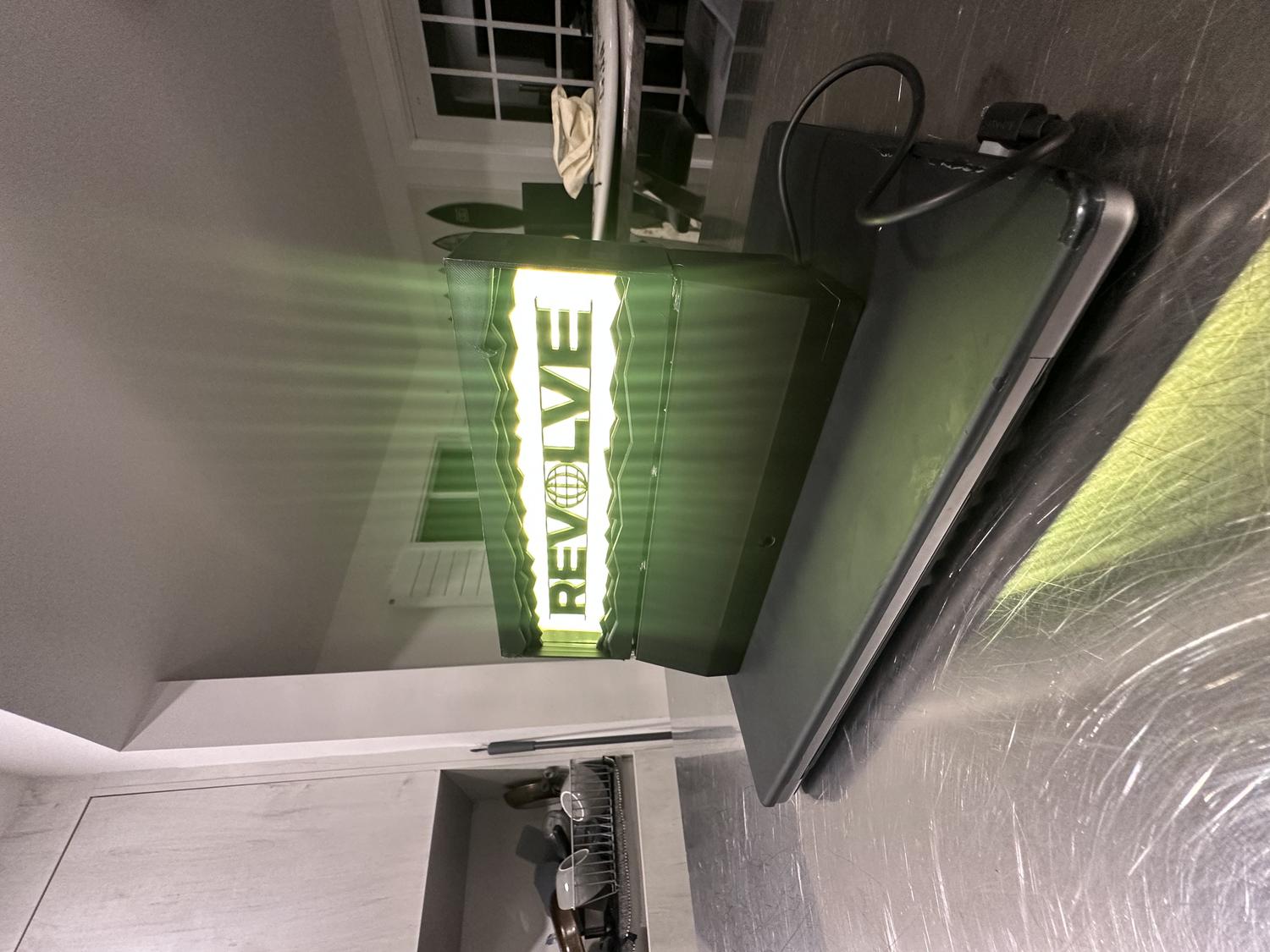
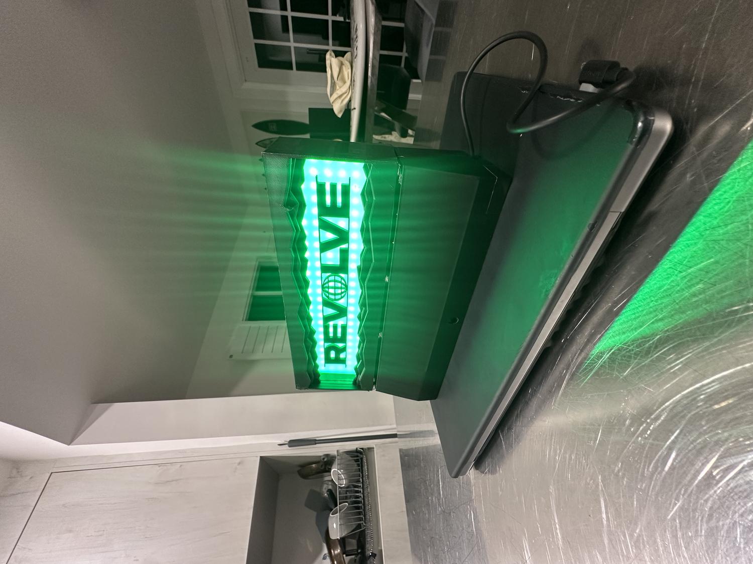
| Button 4 | Green |
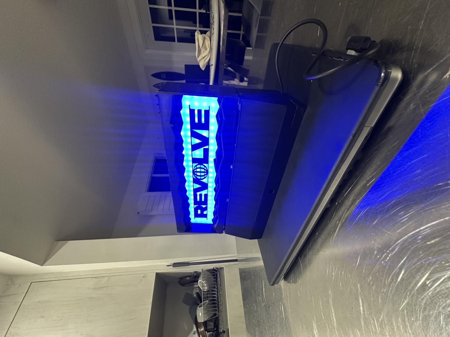
| Button 5 | Blue |
| Button 6 | White |
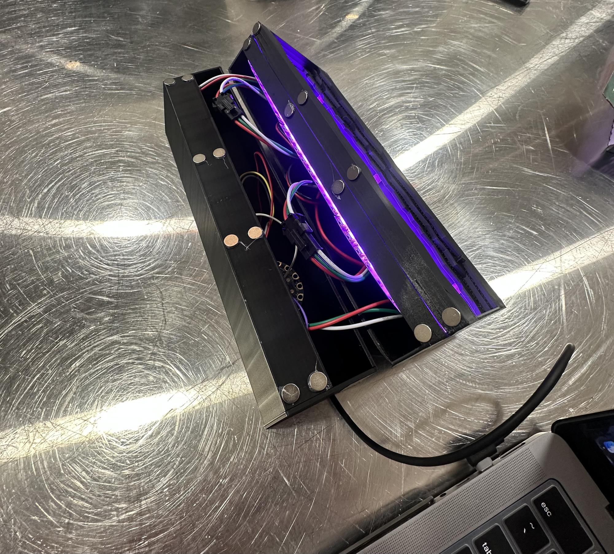
Assembly
- Pieced together all three NeoPixel LED panels and taped down the wires to save space
- Attached the LED panels to the clear PLA frame and began visualizing the full assembly
- Hot glued the REVOLVE letters to the center of the clear frame
- Fit the clear frame snugly into the back holder
- Placed the main front frame over everything and secured it with black duct tape to hold it precisely and cover separation lines
- Fed the IR sensor into the bottom chamber and secured it with duct tape in front of the sensor hole
- Inserted the rest of the circuitry, making sure everything fit neatly inside
- Added 8 magnets to the bottom chamber and 8 to the top frame so the pieces could clip together securely but still be easily disassembled
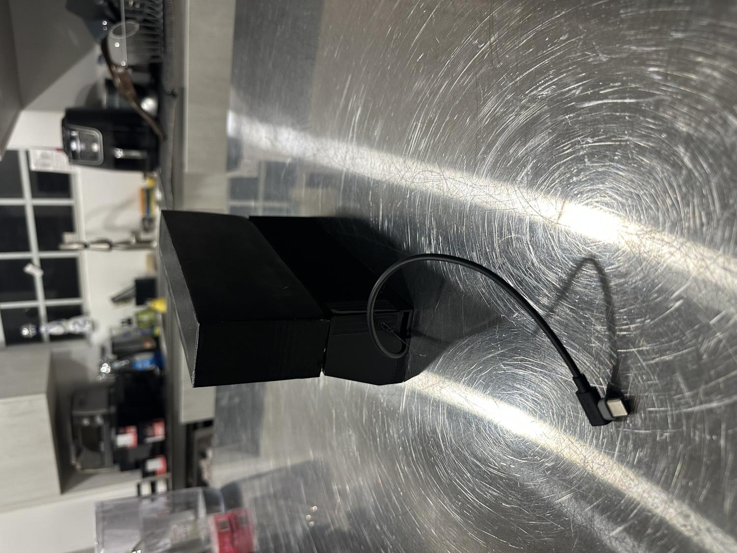
- Attached a side door to cover the bottom chamber opening, using duct tape while leaving space for the power cord to feed out
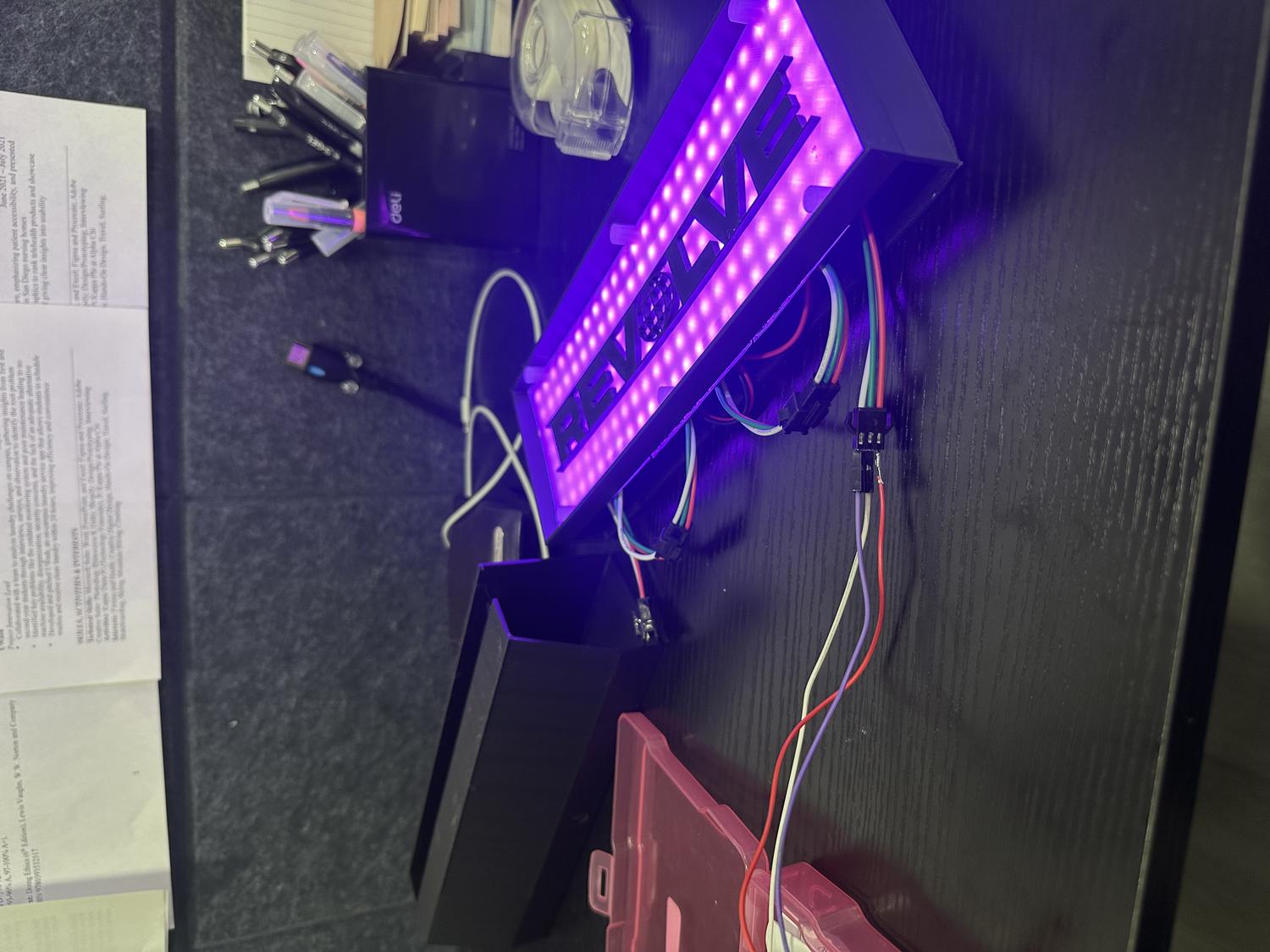
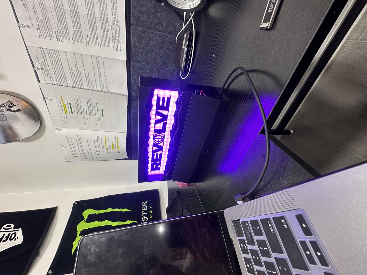
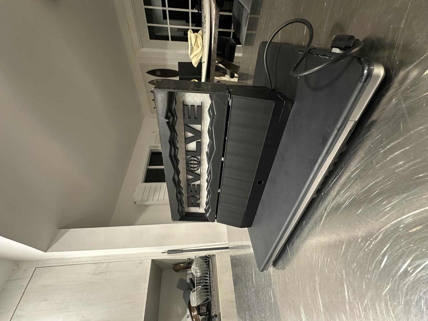
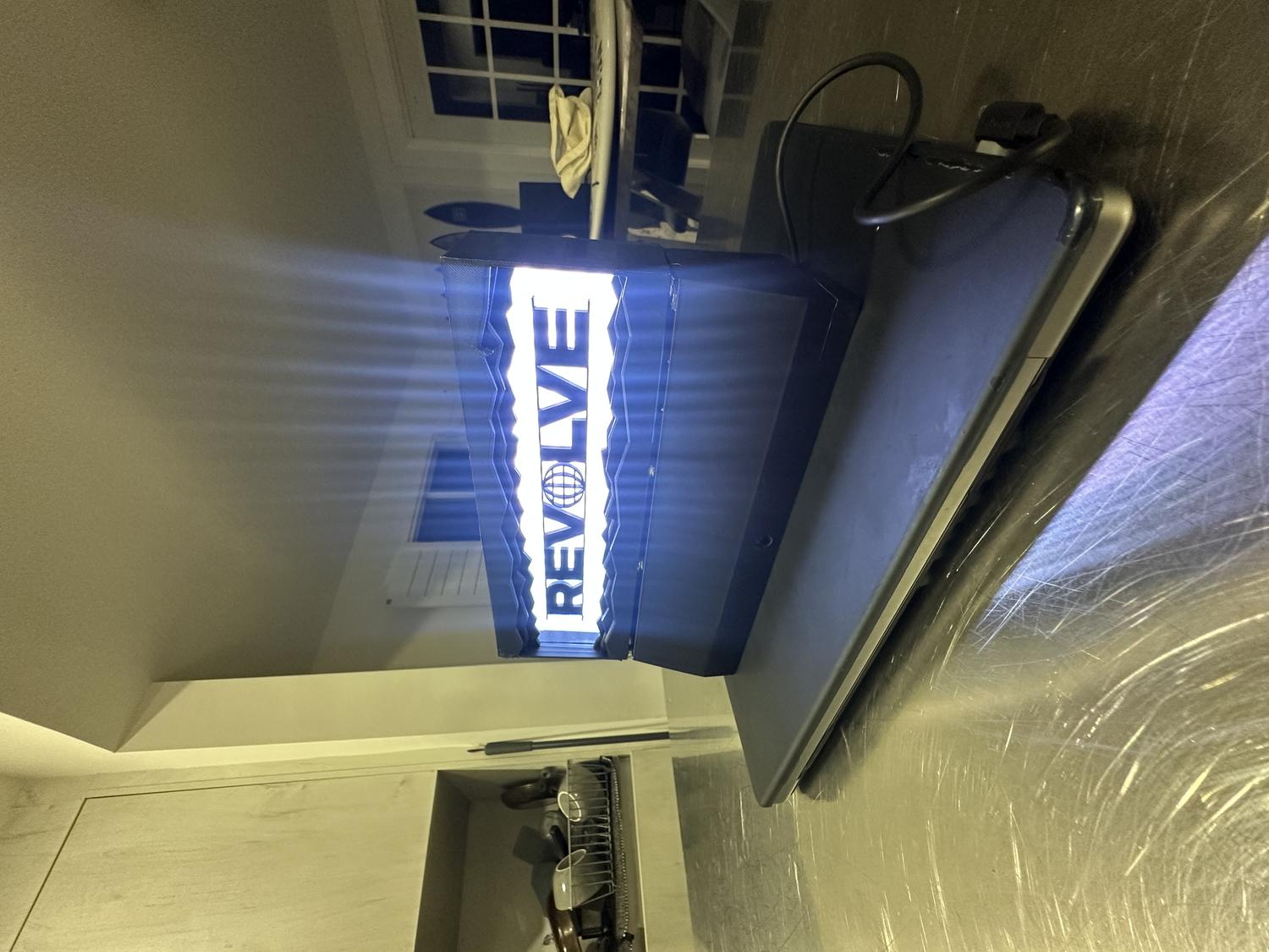
Finished Remote-Controlled Desktop Lightbox

Reflection
What Worked Well:
- The prints came out clean with minimal warping—each piece fit as intended
- The IR sensor functions reliably from 5–10 feet away
- The LEDs shine clearly through the clear PLA and create a strong visual effect
- All hardware fit perfectly in the bottom chamber without feeling cramped
- The magnets are both functional and visually clean, helping the device stay secure
- The final design matched the original vision and looks aesthetic on any desk
Challenges & Limitations:
- Limited RAM on the circuit board restricted the number of features that could be added via remote control
- Originally aimed to use 9 remote buttons for color selection, brightness control, and NeoPixel animations
- The 192 NeoPixels and IR pulse data consumed most of the circuit board's RAM
- Adding more functionality caused the board to overload and crash
- Settled on 6 color options with on/off capability, which was still satisfying
Takeaways:
- Future iterations could use a board with more RAM to support expanded features like animations and brightness control via remote
- The goal was to revise my original REVOLVE LED wall sign (approx. 19"×12") made from cardboard and Cricut-cut letters
- This version was scaled down, 3D printed, and fully enclosed to resemble a polished, functional product
- The final piece is durable, cleanly assembled, and visually high-quality
- Thorough planning led to a result that exceeded expectations
- Future versions could support more remote functions with additional inputs/outputs
- Despite hardware limitations, this was a successful and complete first prototype that met all core design goals