Spinal Fusion CAD
Project Overview
I created this project to strengthen my SolidWorks skills through a medical-device application. After becoming interested in spine-focused med-tech companies in Carlsbad, California, I wanted to move beyond basic CAD practice models to something combining anatomy, medical imaging, and implant design.
The goal was to design a conceptual patient-specific L4–L5 interbody fusion cage using anatomy derived from a public CT dataset, working through a full CAD workflow: CT segmentation and anatomical measurements, part modeling, assemblies, fixation geometry, technical drawings, and animation.
The cage is designed as an anterior lumbar interbody fusion (ALIF) device: it's meant to be inserted through an anterior surgical approach, which is why the fixation screws are positioned on the anterior face rather than posteriorly or laterally.
This project was completed independently after graduation as a learning exercise. It is intended for educational and design practice only and is not a clinically validated medical device. The geometry and design decisions should not be interpreted as recommendations for clinical use.
3D Slicing CT Scans
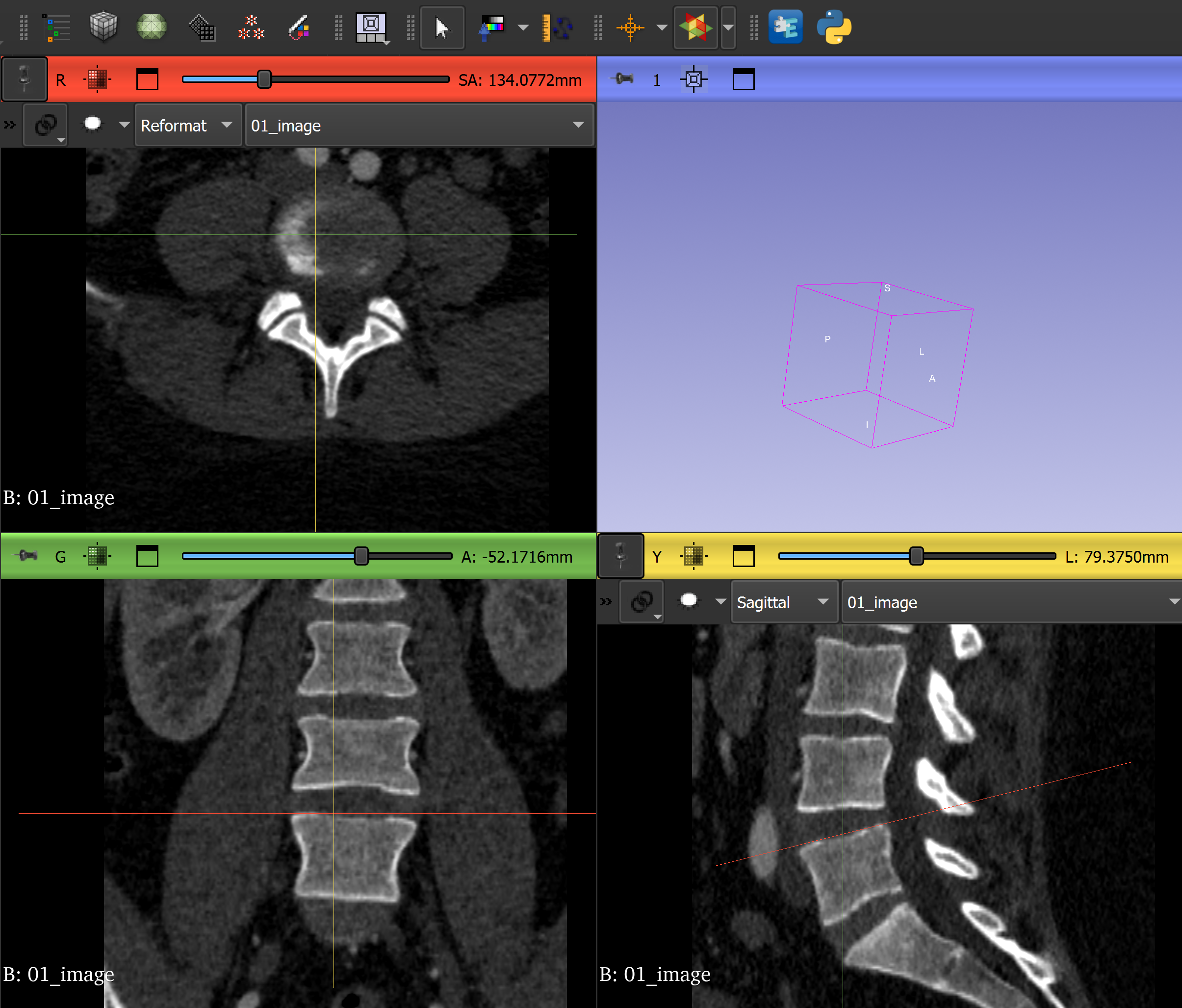
Patient-specific spine implants can use CT imaging to inform implant geometry rather than relying on standardized sizes. I downloaded a publicly available lumbar CT dataset of two matched .mha files: the patient’s CT image volume (image.mha) and its segmentation mask (mask.mha). I imported both into 3D Slicer to cross-reference the imaging data and segmentation while isolating the target anatomy.
I selected the L4–L5 level because it provided a clear lumbar intervertebral space where I could study the relationship between two adjacent vertebral endplates and translate that anatomy into a cage design.
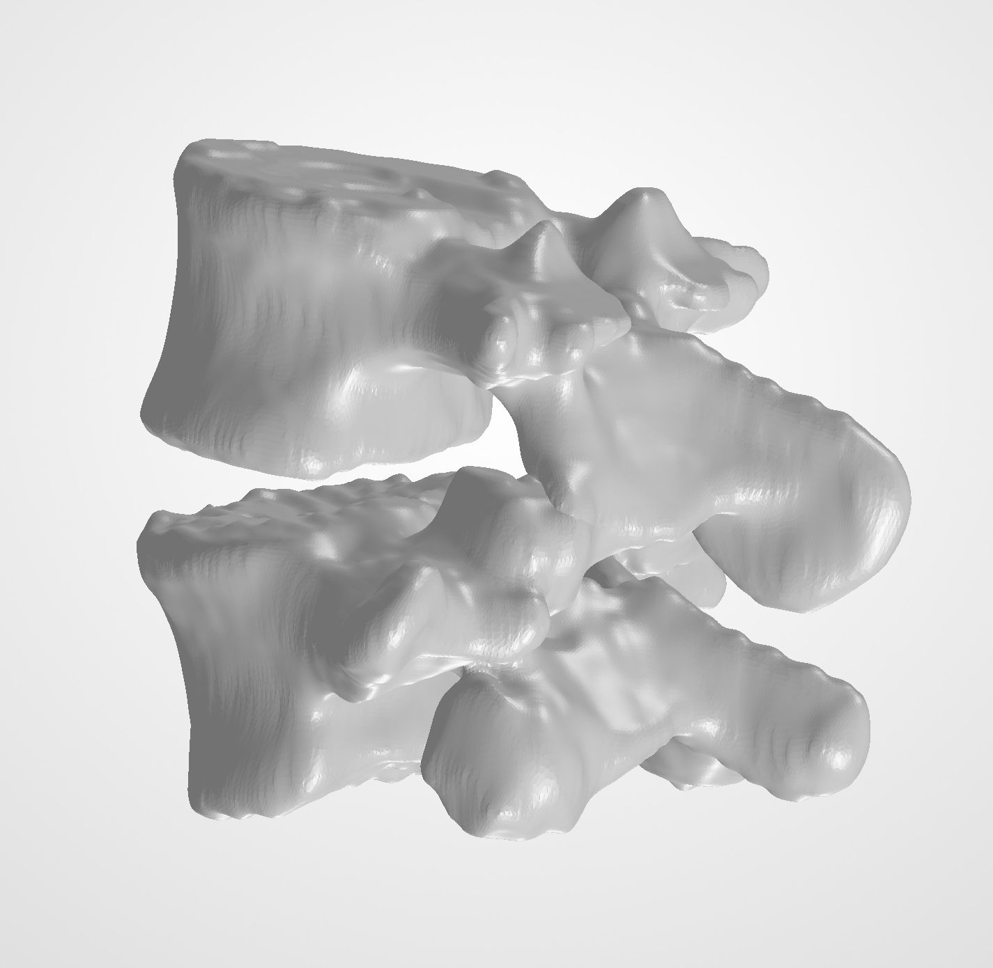
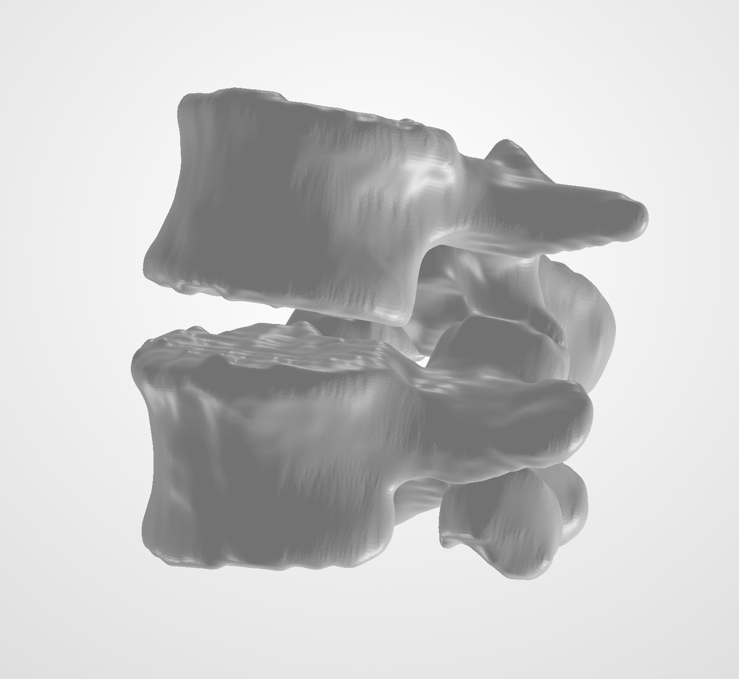
Using the sagittal, axial, and coronal CT views, I identified L4 and L5 and created separate segmentations. I used Threshold, Islands, Scissors, and Smoothing to isolate and refine the anatomy while preserving the relative position and orientation of the vertebrae.
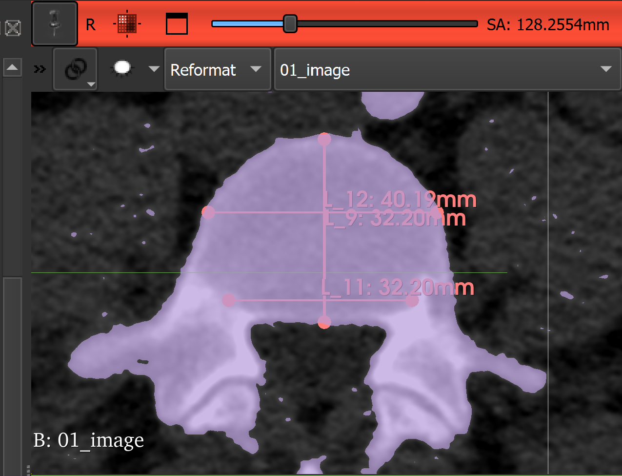
I also experimented with 3D Slicer’s measurement tools to better understand the anatomy and disc-space geometry. These served as a learning and cross-reference step; the dimensions driving the final CAD design were taken from the exported anatomy in SolidWorks.
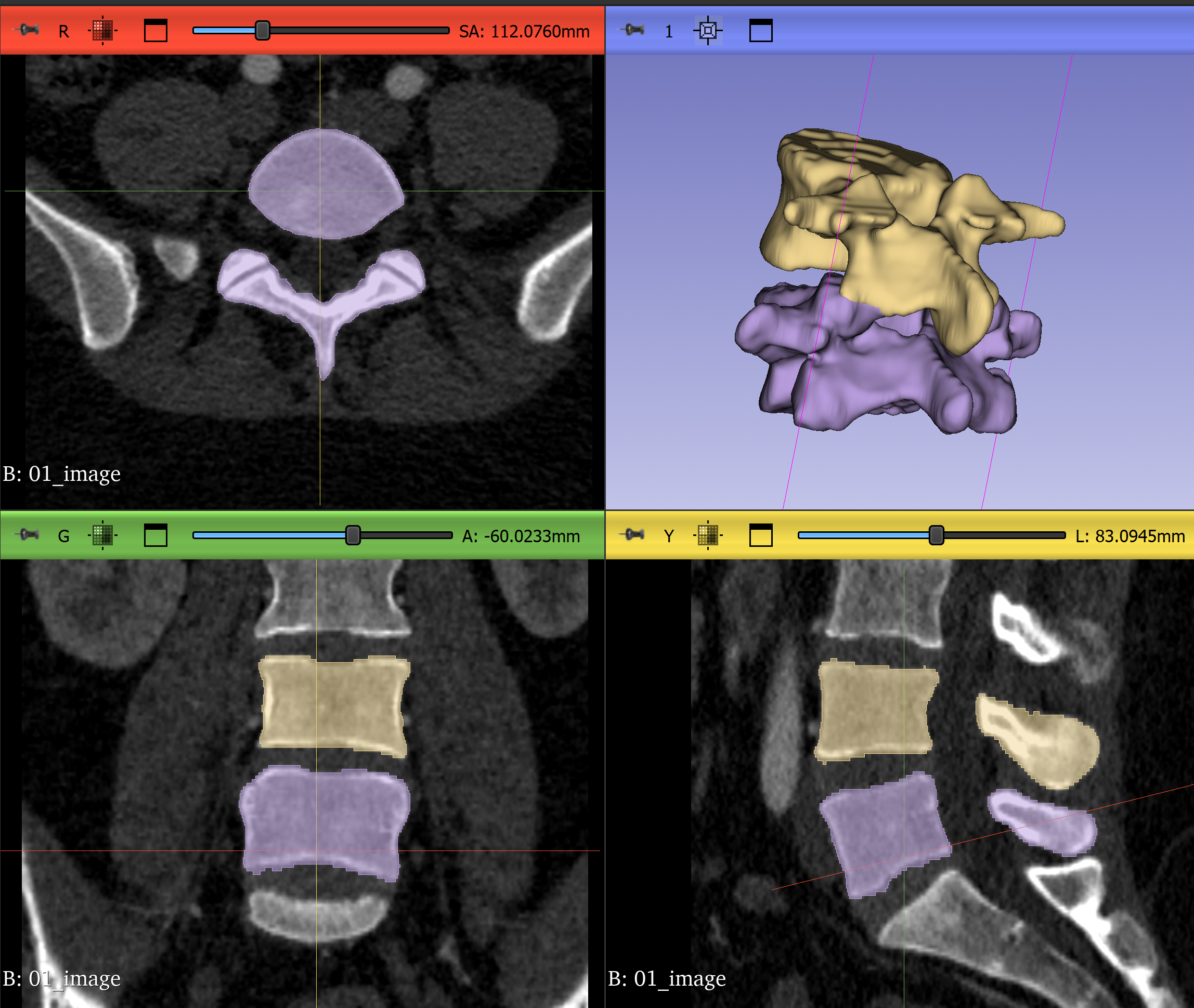
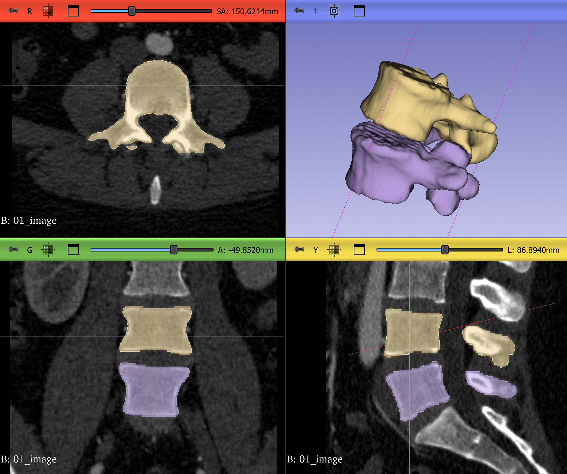
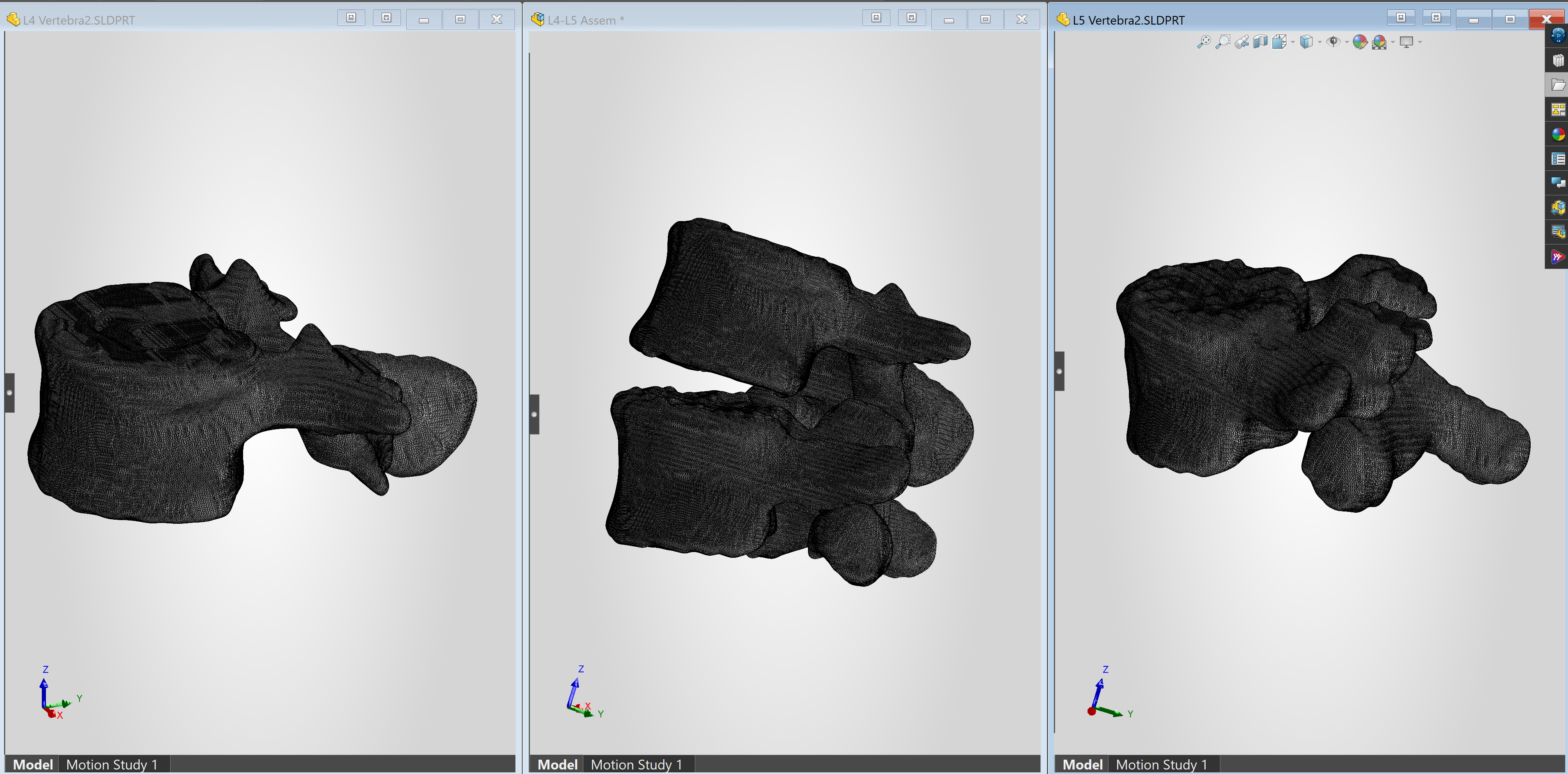
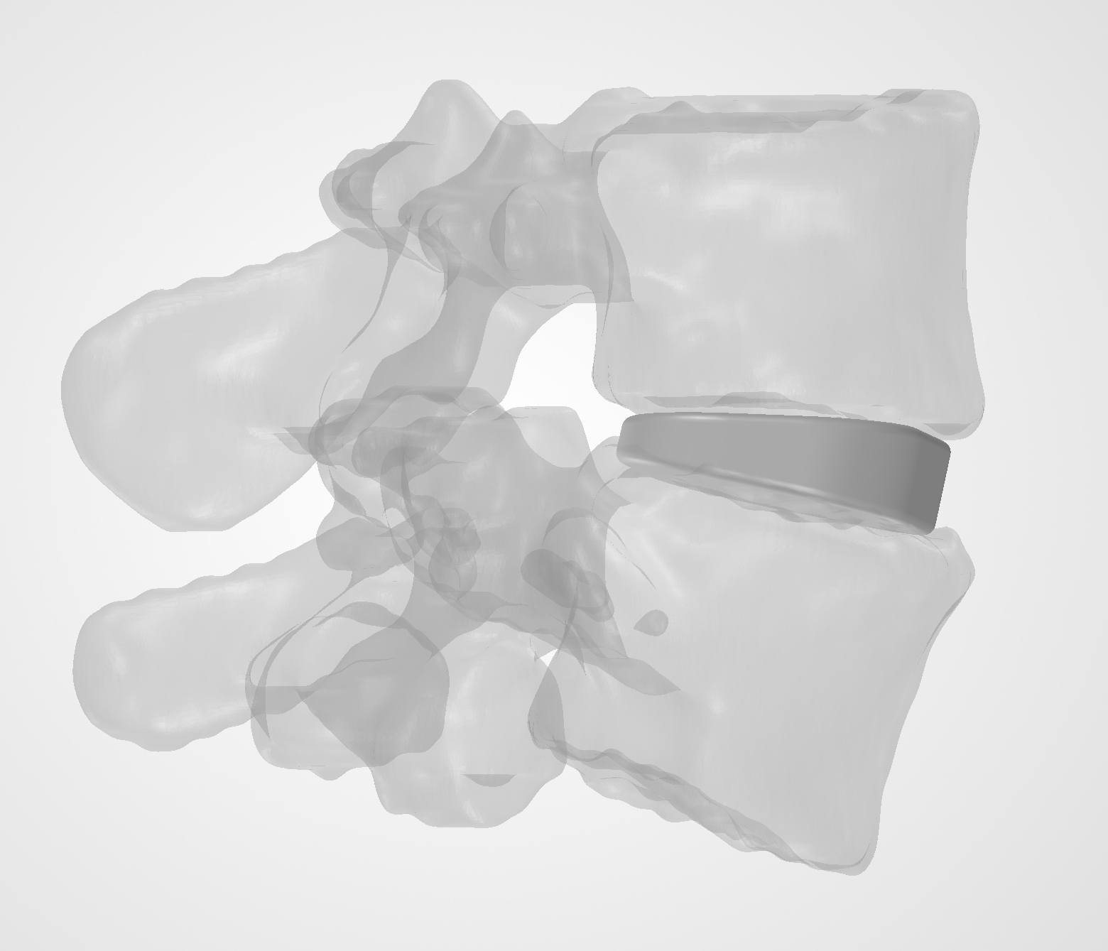
Once the segmentations were complete, I exported L4 and L5 as STL files and imported them into SolidWorks, positioning them in an assembly that maintained their relative anatomy.
Defining the Cage Dimensions
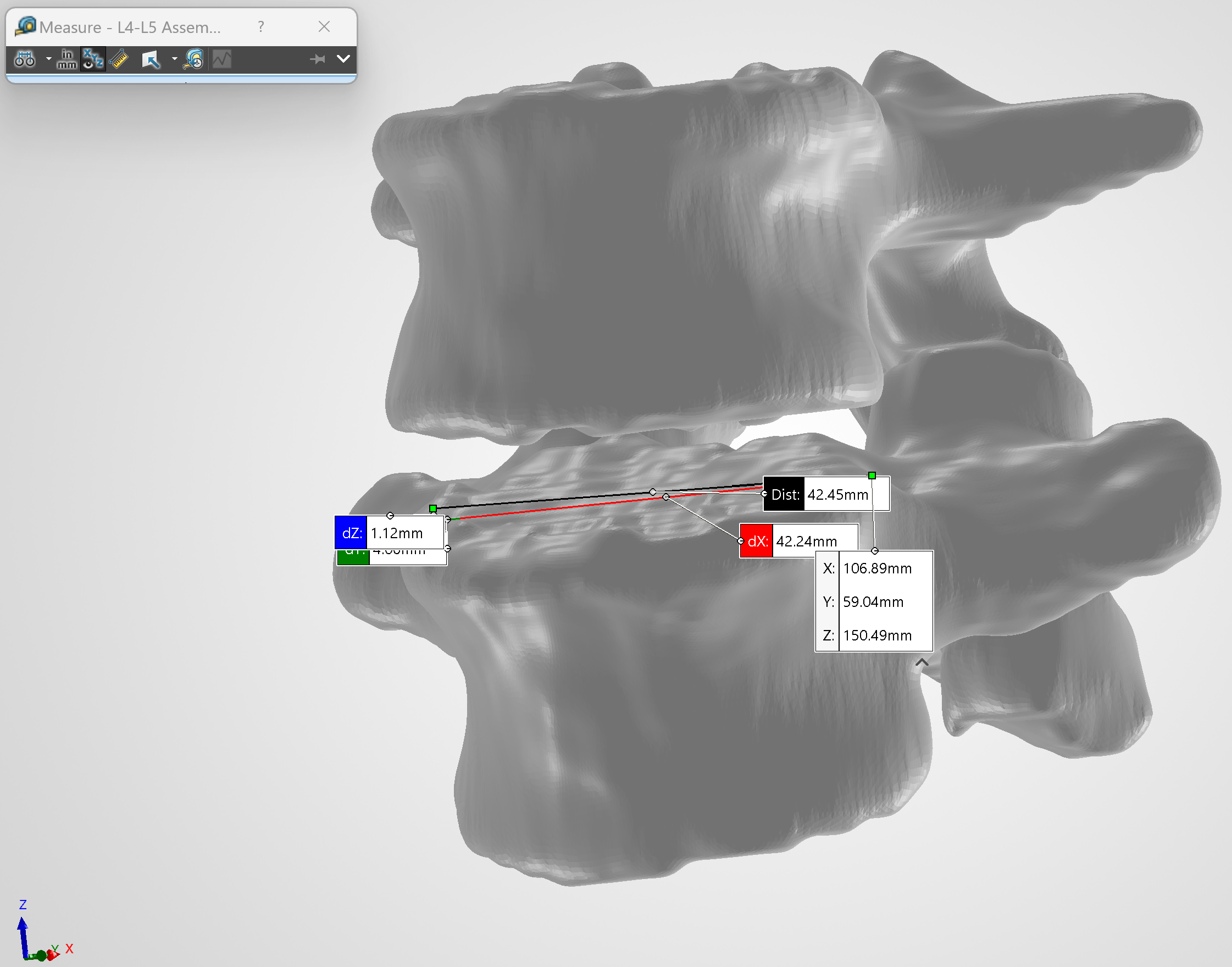
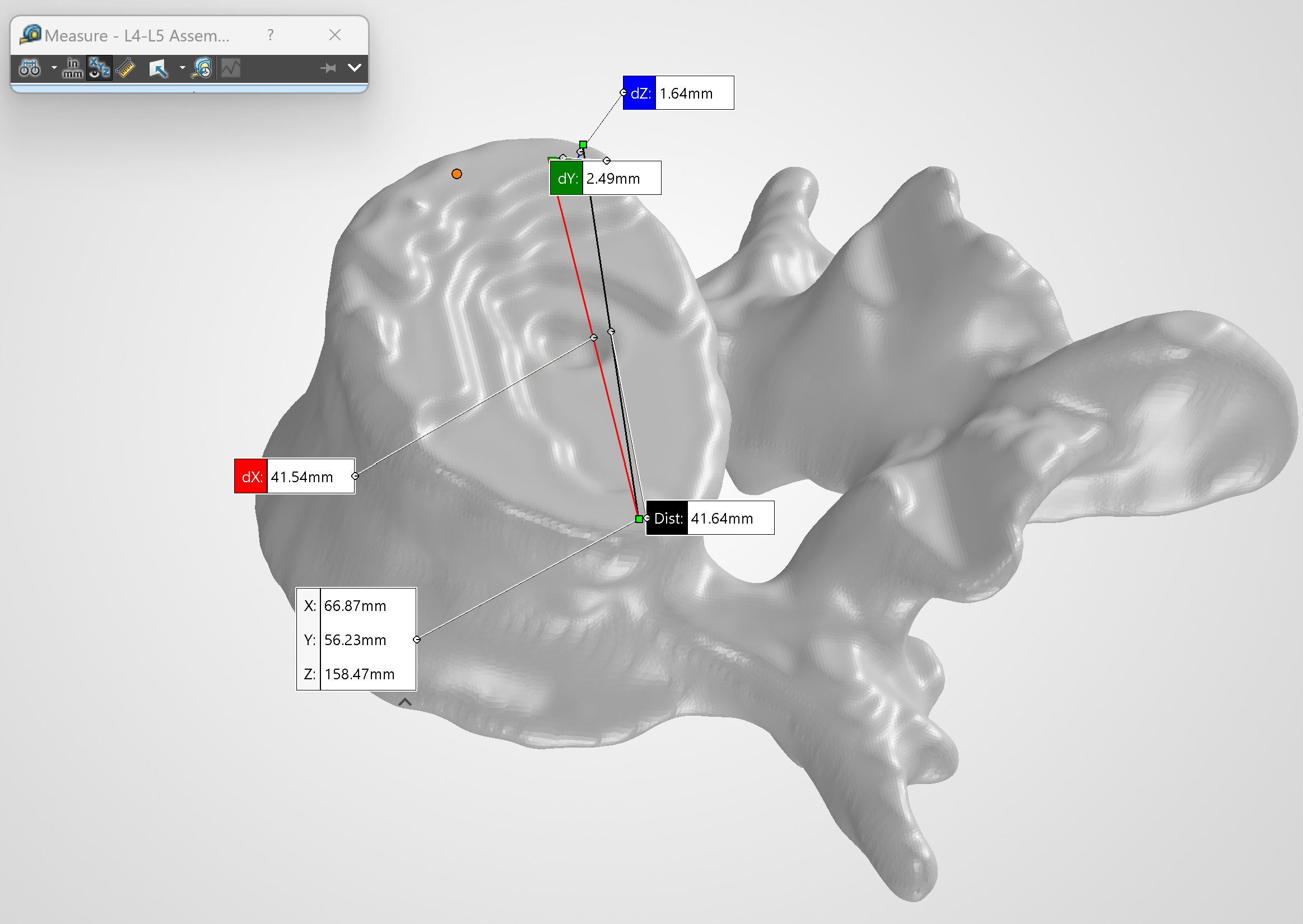
With L4 and L5 inside SolidWorks, I measured the opposing endplates and L4–L5 disc space to establish the design envelope for the cage.
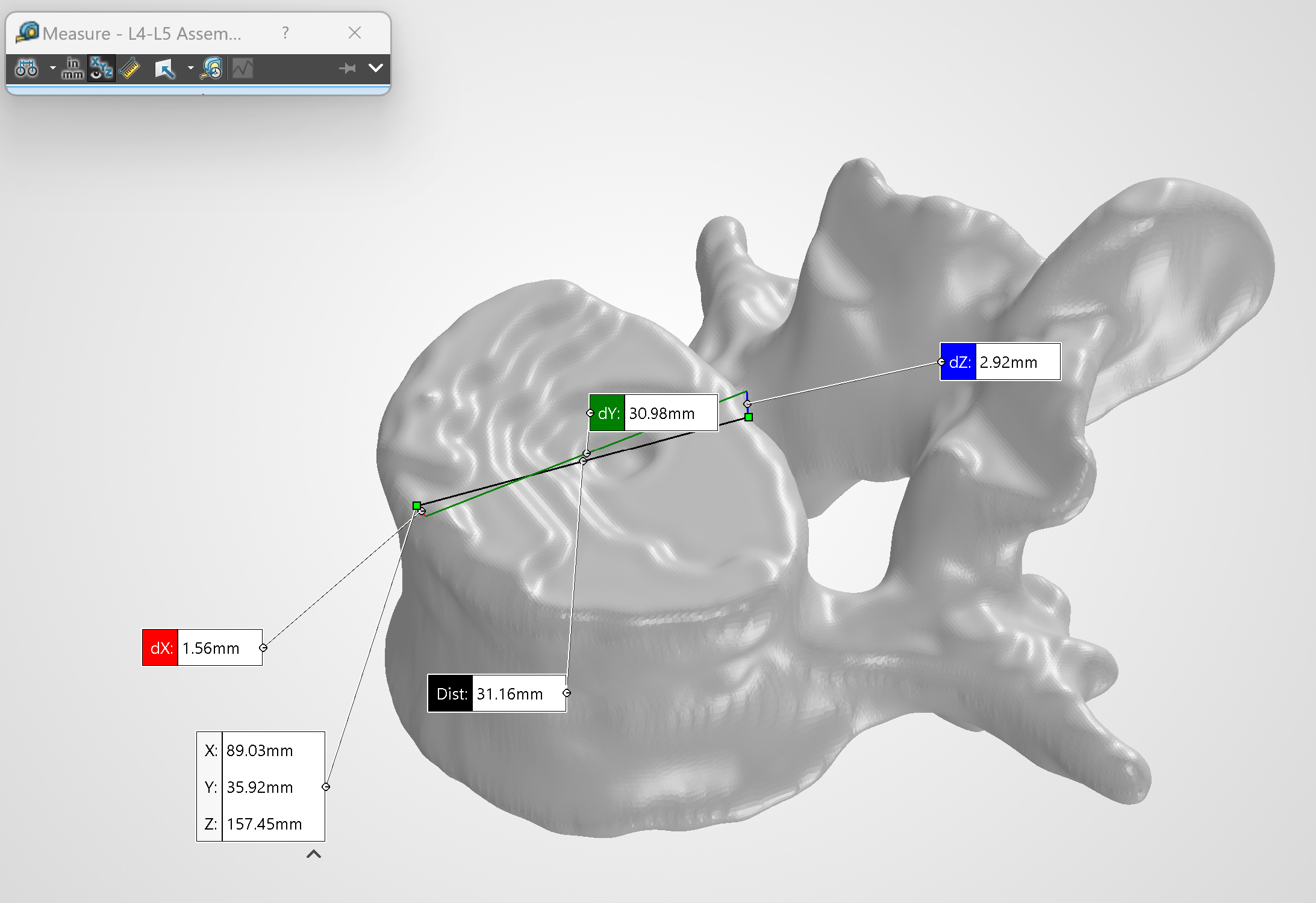
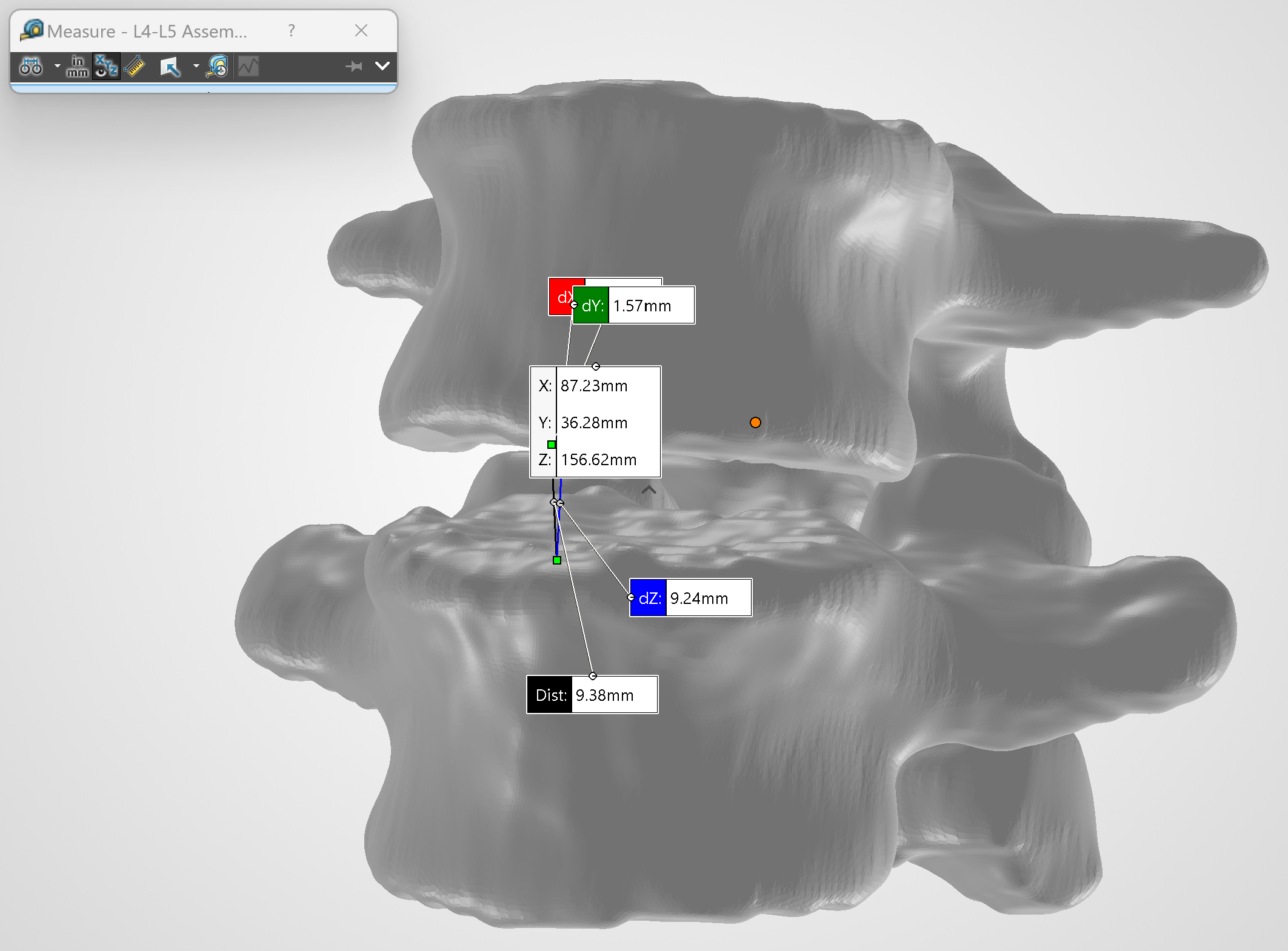
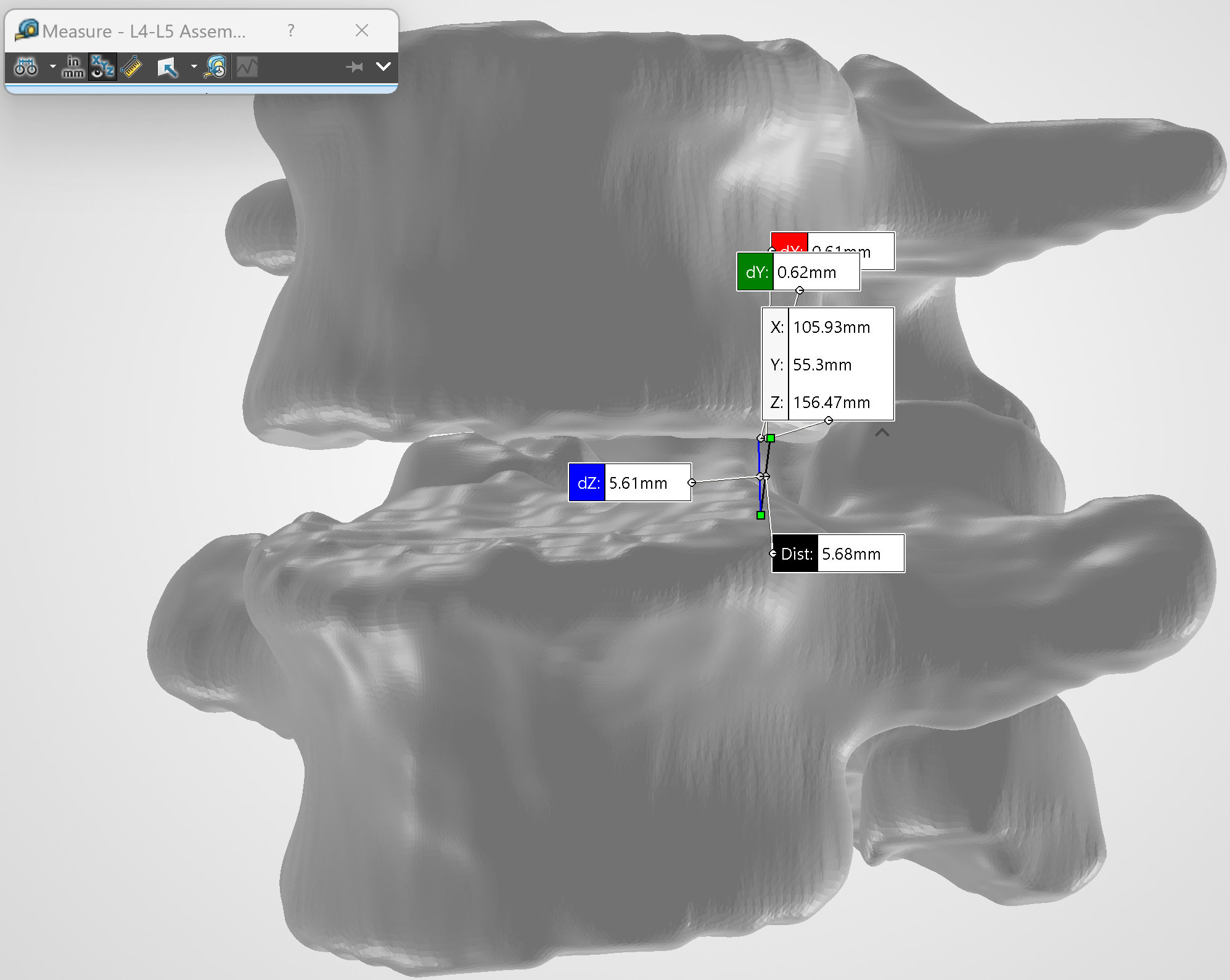
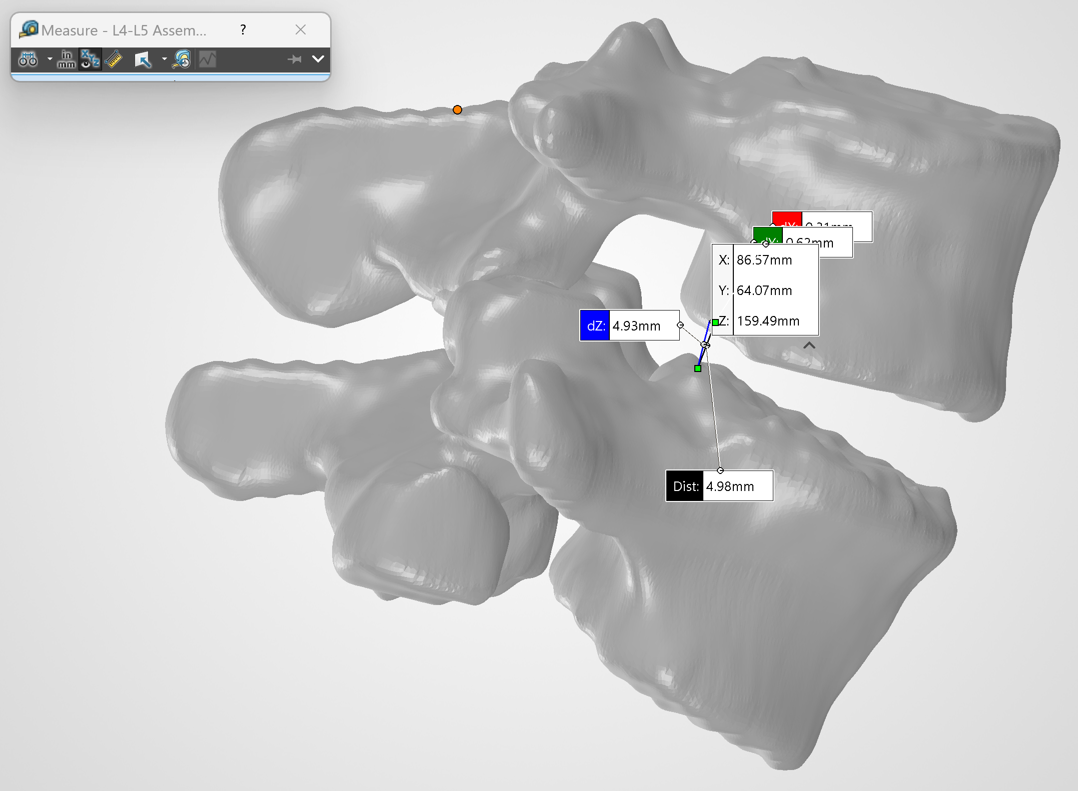
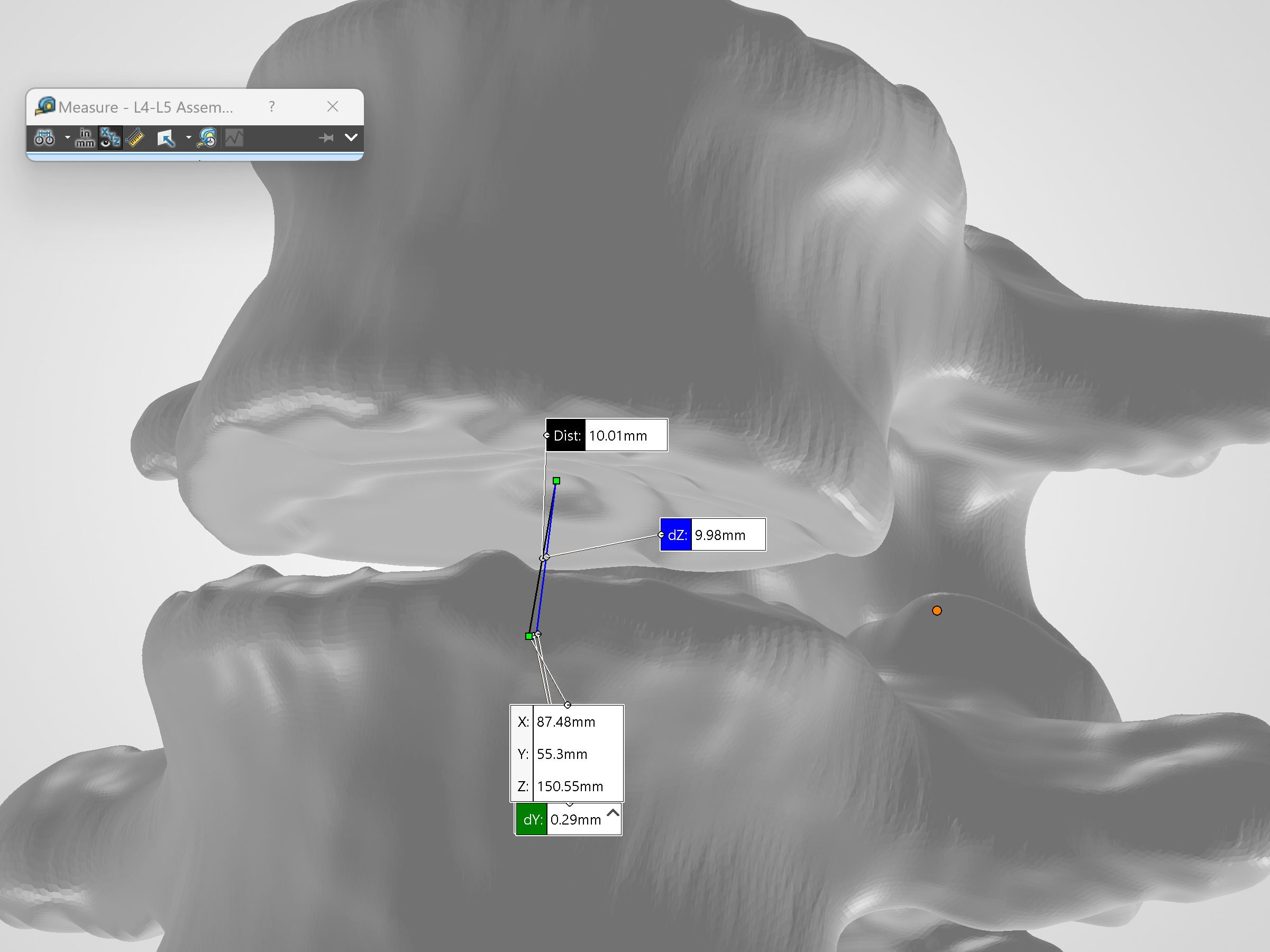
Measurements included:
| Measurement | Value |
|---|---|
| L5 superior endplate AP depth | 32.05 mm |
| L5 superior endplate width | 42.45 mm |
| L4 inferior endplate AP depth | 31.16 mm |
| L4 inferior endplate width | 41.64 mm |
| Anterior disc-space height | 9.38 mm |
| Posterior disc-space height | 4.98 mm |
| Patient-left disc-space height | 5.68 mm |
| Patient-right disc-space height | 6.07 mm |
| Central disc-space height | 10.01 mm |
I intentionally did not make the cage footprint equal to the full measured endplate dimensions. Using the smaller L4 inferior endplate as the limiting reference, I targeted a footprint of approximately 36 mm mediolateral × 26 mm AP. Against the 41.64 mm × 31.16 mm L4 endplate, that gave roughly 2.82 mm of mediolateral and 2.58 mm of AP clearance per side, about a 2–3 mm perimeter inset.
The offset keeps the footprint inside the endplate boundary rather than at its maximum dimensions, reducing the risk of edge overhang while preserving a broad contact area. I kept refining it as the design evolved, using the patient anatomy and assembly fit as visual references.
Once I had established the dimensional envelope and intended clearance, I began building the cage.
Building the Base Geometry
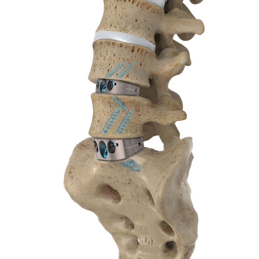
I looked for inspiration online and found these spinal fusion cages sitting exactly where I was going to build my model. Many of my design choices were taken from this design.
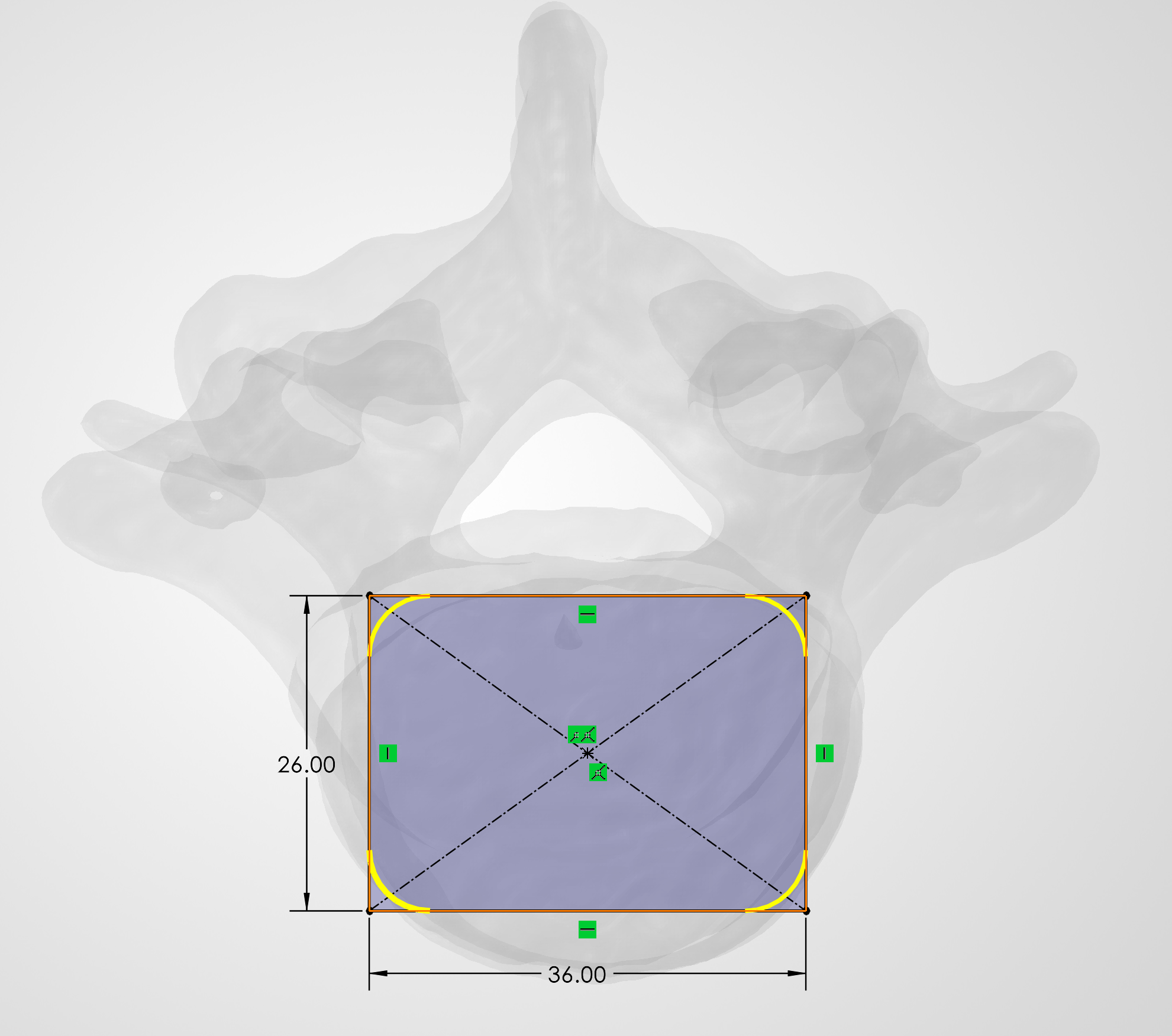
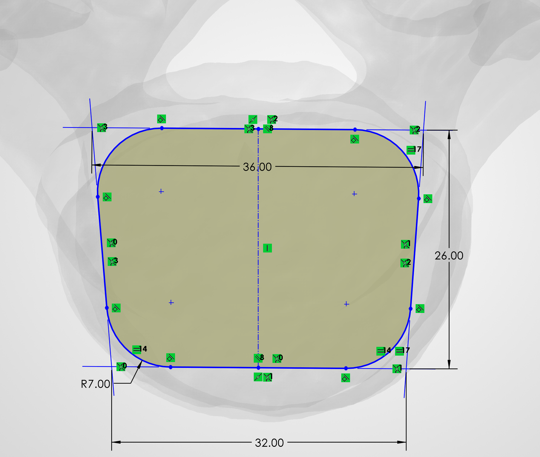
- Sketched the initial cage footprint and used sketch fillets to create rounded corners appropriate for the overall implant form.
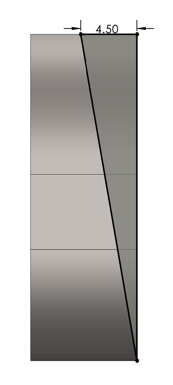
- Tapered the footprint so the anterior and posterior widths were different, using construction geometry and sketch relationships to maintain symmetry.
- Iterated on the footprint as the design developed, including increasing the corner radii to produce a smoother overall profile.
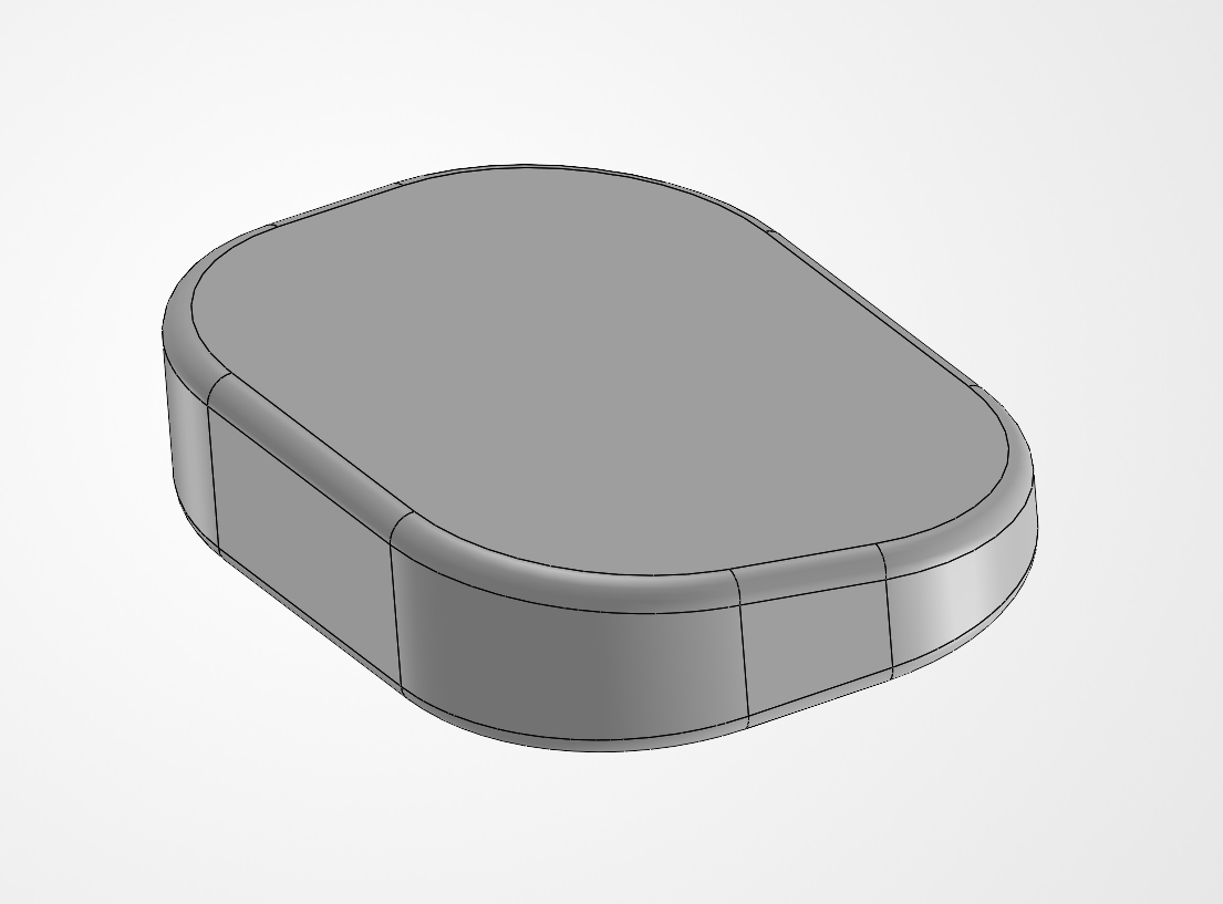
- Extruded the footprint to establish the initial solid body before modifying its superior surface.
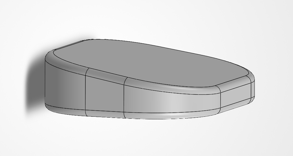
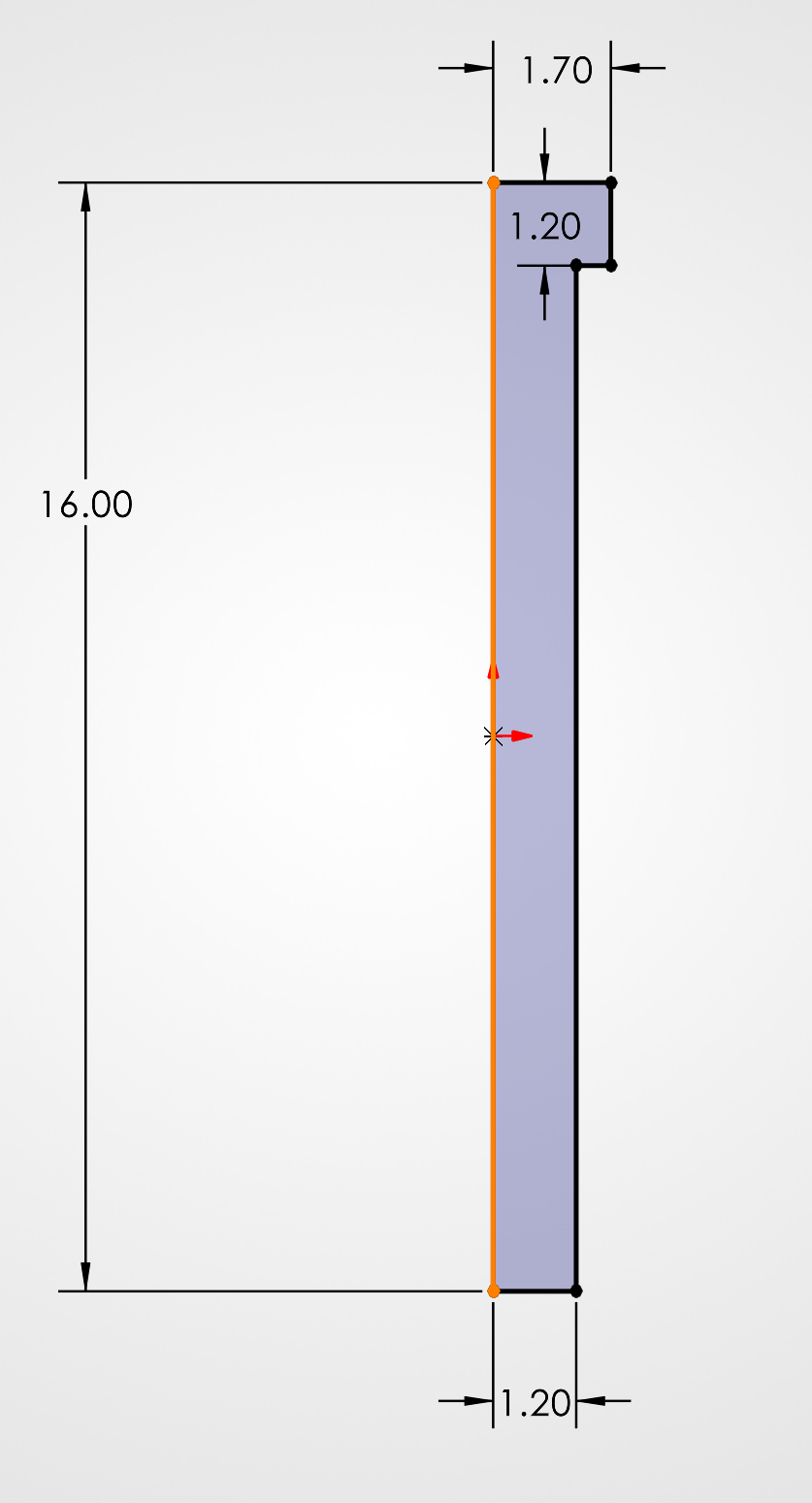
- Created a side-profile sketch and used a Cut-Extrude for the wedge-shaped superior surface, with approximately 9.82° of slope so the cage height changes across its AP direction.
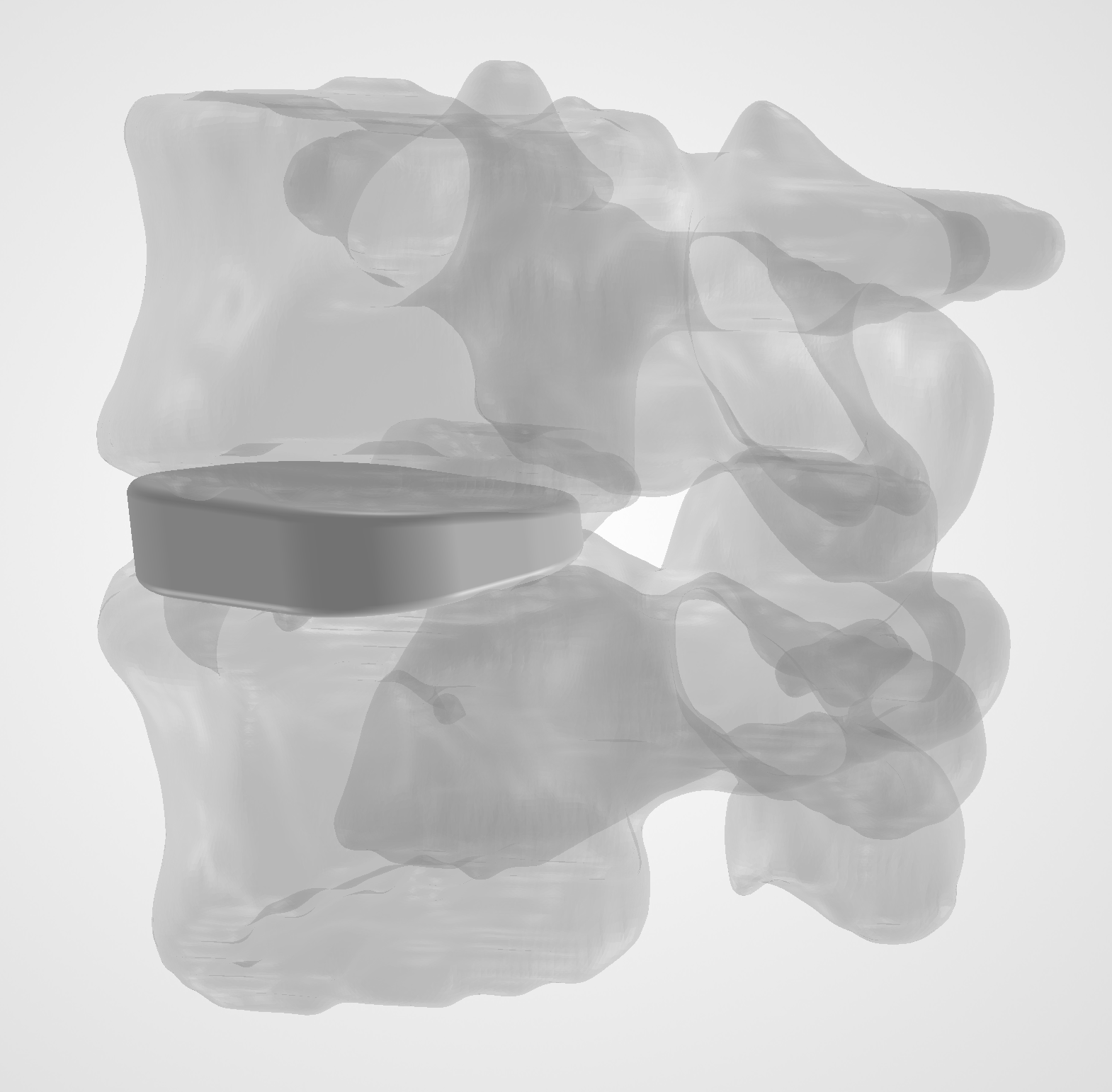
- Added fillets around the exterior edges and repeatedly checked the part against the L4–L5 assembly to evaluate its overall fit and proportions.
Fixation & Detailed Geometry
Fixation Holes
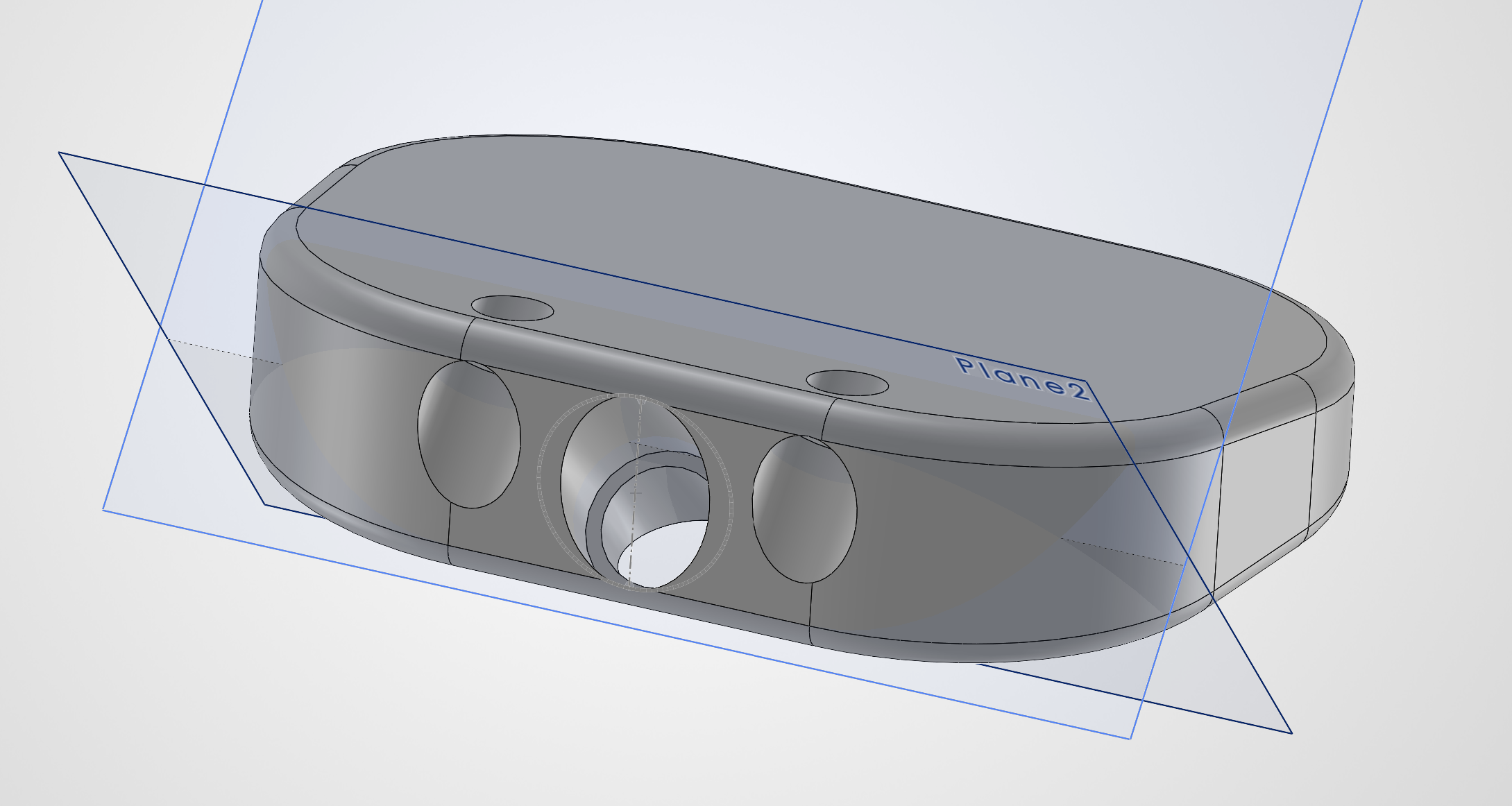
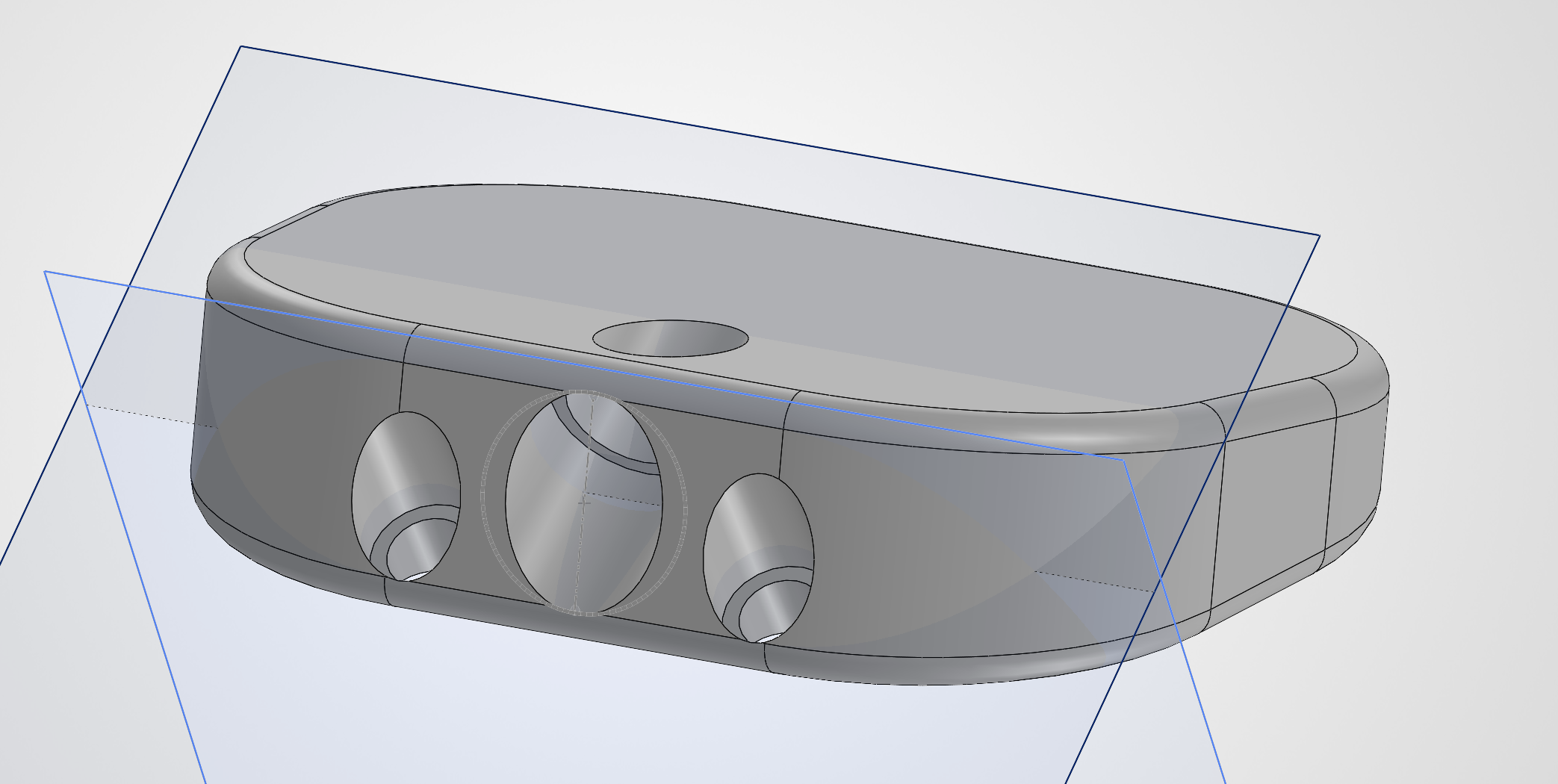
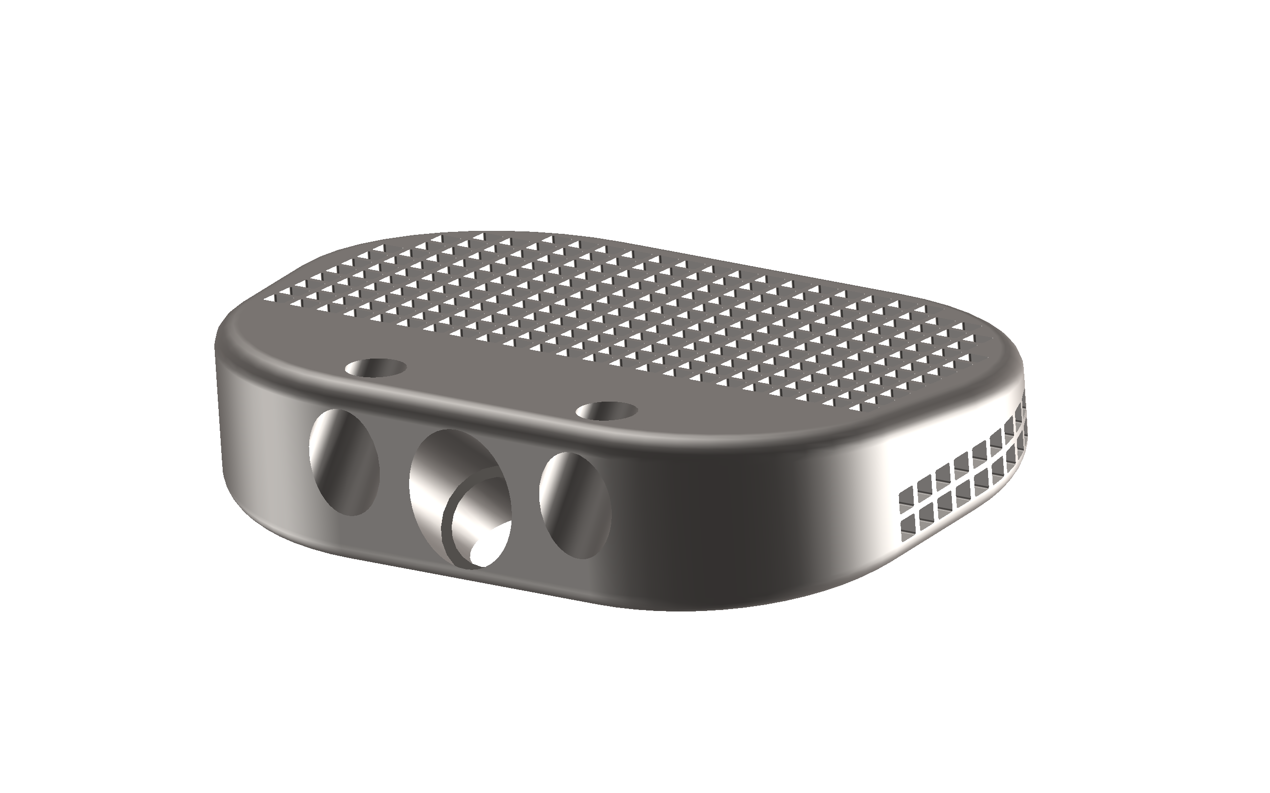
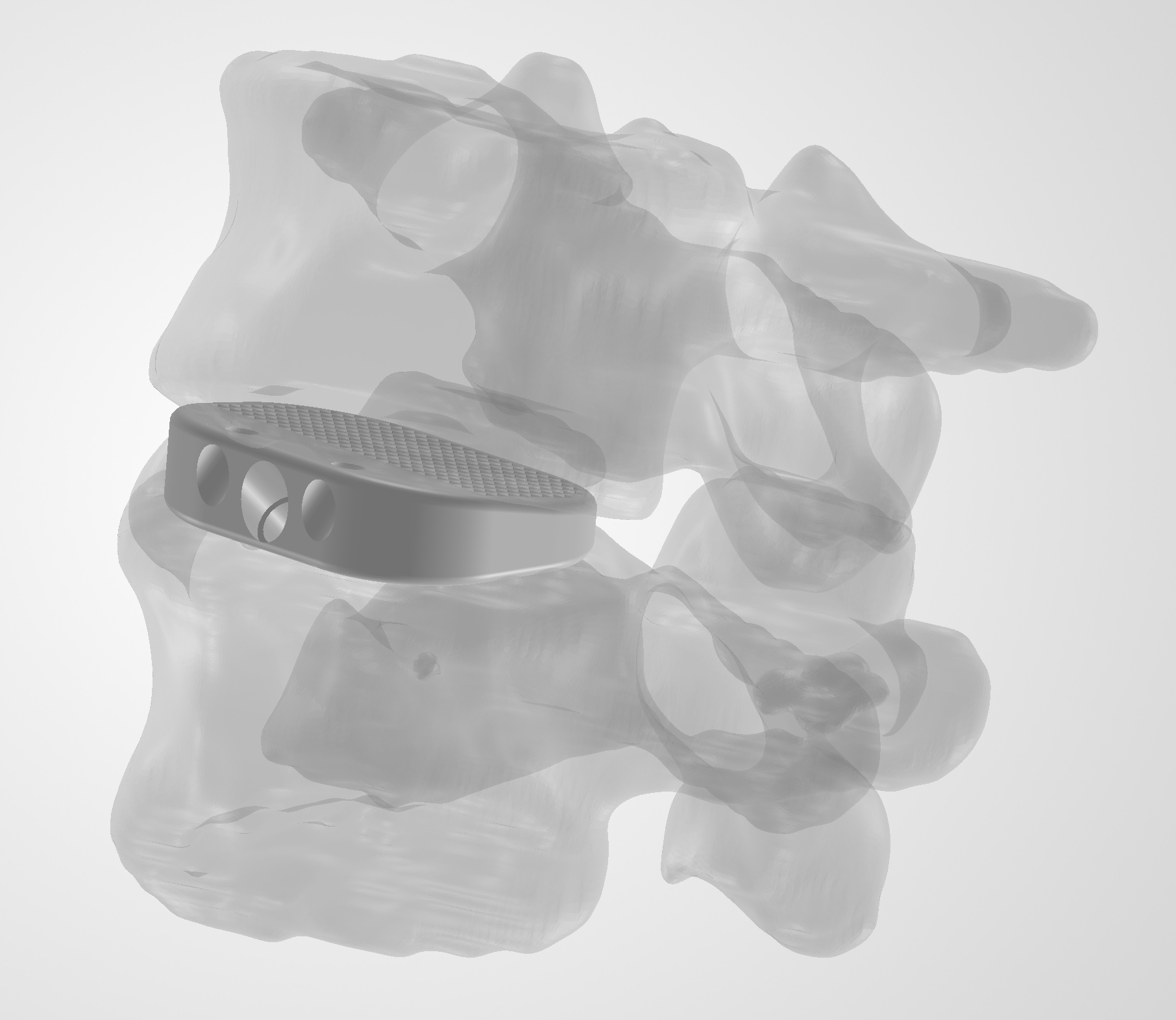
- Added three anterior fixation paths: one larger central fixation hole and two smaller lateral holes.
- The central fixation hole uses a stepped Ø5.00 mm / Ø4.00 mm geometry; the lateral holes use Ø3.50 mm / Ø2.50 mm. Both are conceptual proportions rather than a validated screw specification.
- Created angled reference planes to control the trajectories of the fixation holes rather than cutting them perpendicular to the anterior face.
- Positioned sketches on the angled planes and aligned their centers with the corresponding anterior-face geometry before creating the cuts.
- Used a shallow blind cut for the larger screw-head region followed by a Through All Cut-Extrude for the narrower screw-body path.
- The central fixation trajectory sits at approximately 39.82° relative to the inferior surface, the lateral trajectories at approximately 45.18°. Both angle into the adjacent vertebral bodies rather than running straight posteriorly.
- Returned to the L4–L5 assembly throughout the process to visually evaluate the trajectories against the surrounding anatomy.
Lattice-Style Geometry
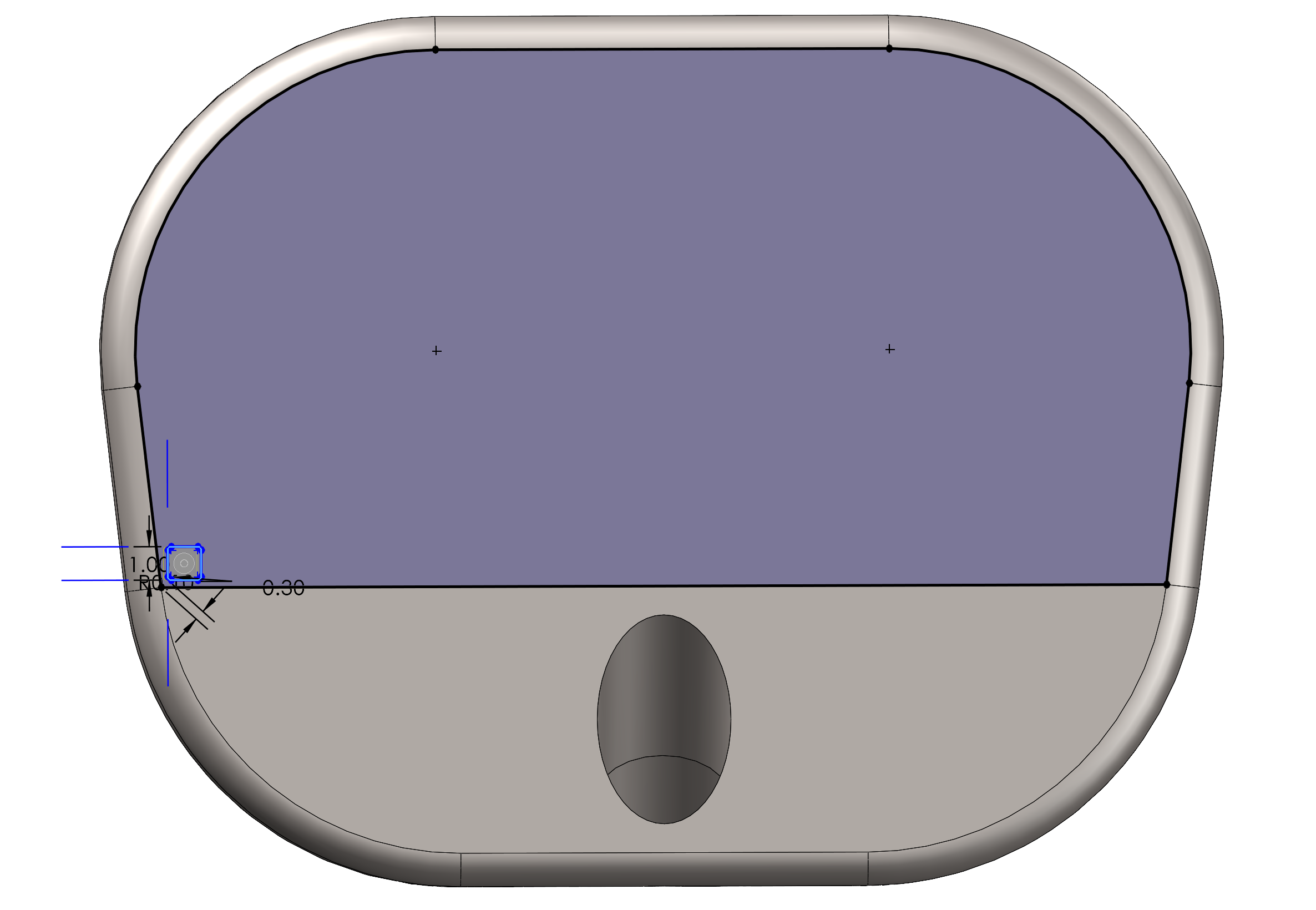
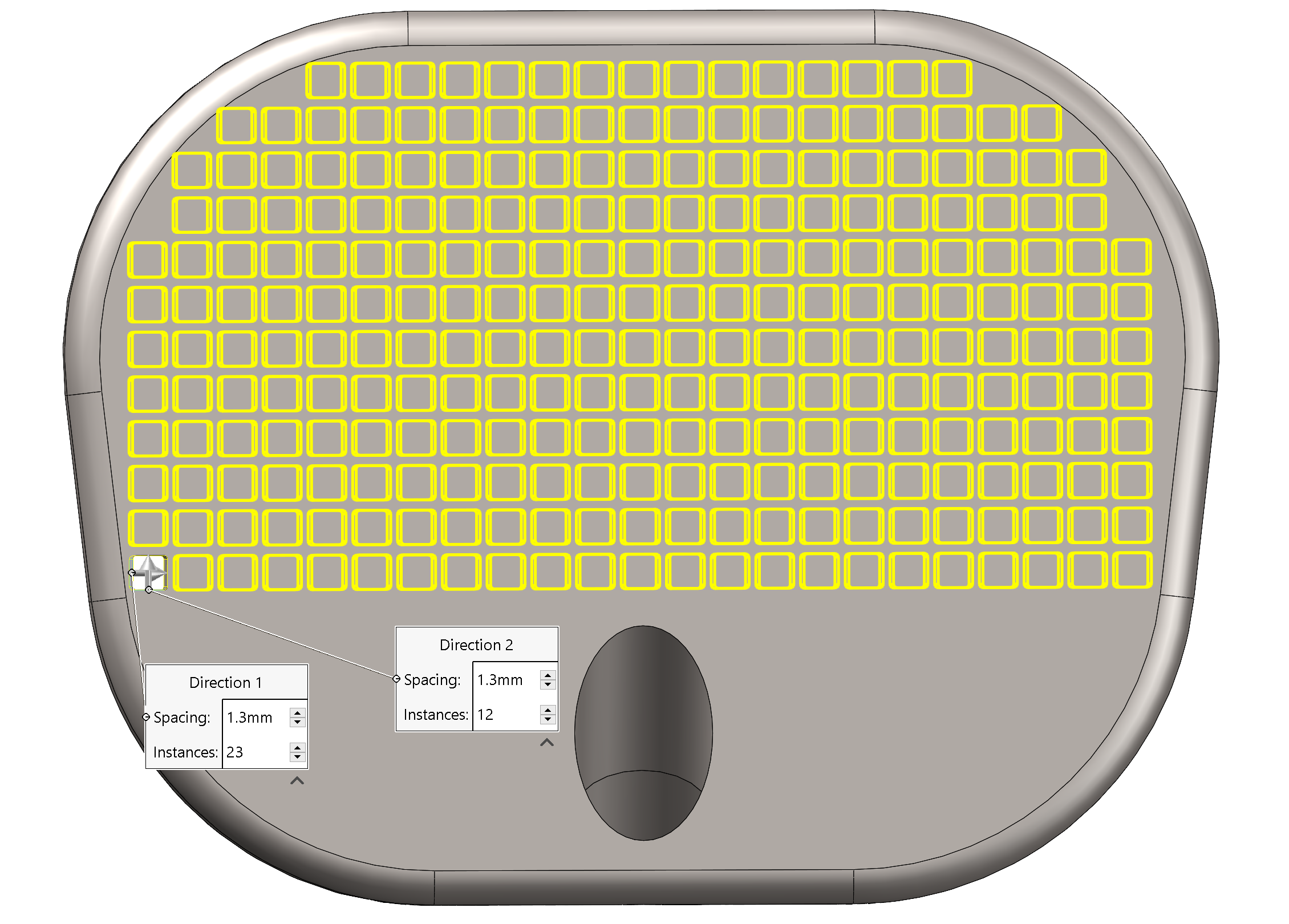
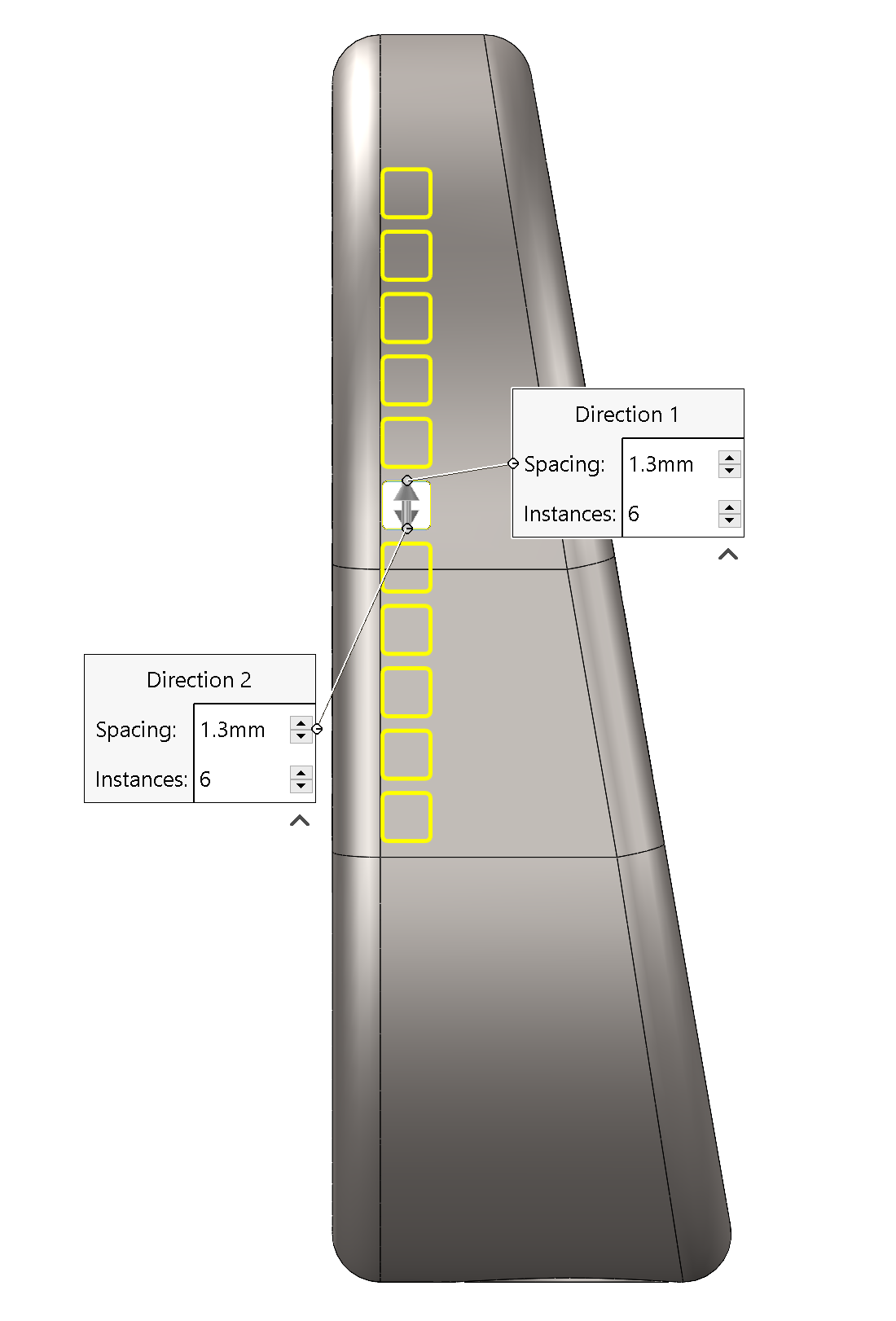
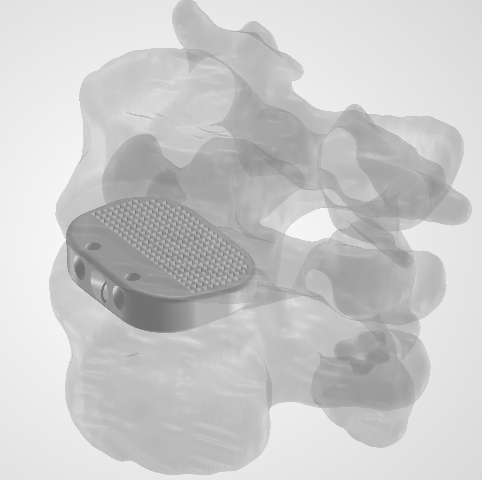
- Added a lattice-inspired region because porous structure matters in interbody cages: interconnected voids support bone ongrowth and ingrowth, open pathways for fusion, and allow stiffness to be tuned rather than fixed.
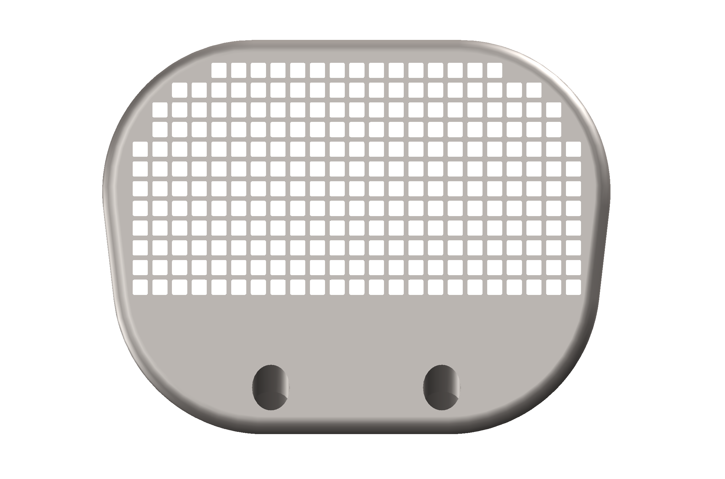
- Created a 1.00 × 1.00 mm rounded-square opening and cut it through the surface.
- Used Linear Pattern to repeat the feature across the cage, selectively skipping instances near the outer boundary and fixation geometry.
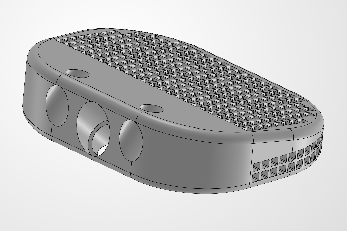
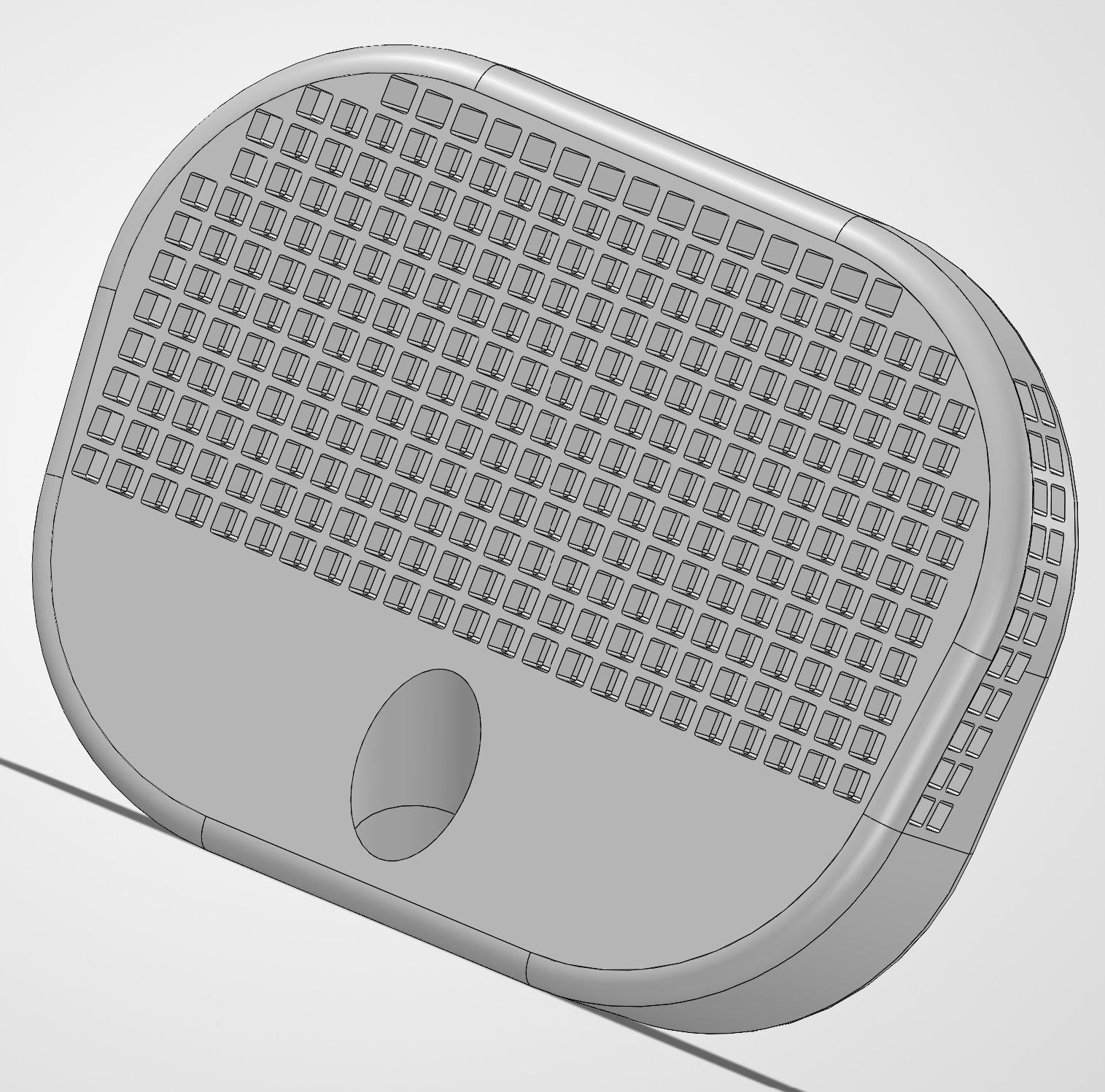
- Repeated the patterning process from additional faces so the intersecting cuts created an internal lattice-like structure rather than only a surface texture.
- I built it manually rather than using a dedicated lattice-generation feature. As a SolidWorks learning project, the point was to demonstrate Cut-Extrude, Linear Pattern, skipped instances, and intersecting feature geometry myself.
- The result is a conceptual approximation of that architecture, not a biomechanically optimized or clinically validated one. I did not evaluate its mechanical performance.
Material & Final Assembly
- Assigned Ti-6Al-4V titanium alloy to the cage, a material commonly associated with orthopedic implant applications.
- Adjusted the part appearance to give the final model a metallic titanium-like finish.
- Modeled conceptual fixation screws specifically for the hole geometry rather than using stock SolidWorks components.
- Added the screws to the assembly and used mates to position them along the intended fixation trajectories.
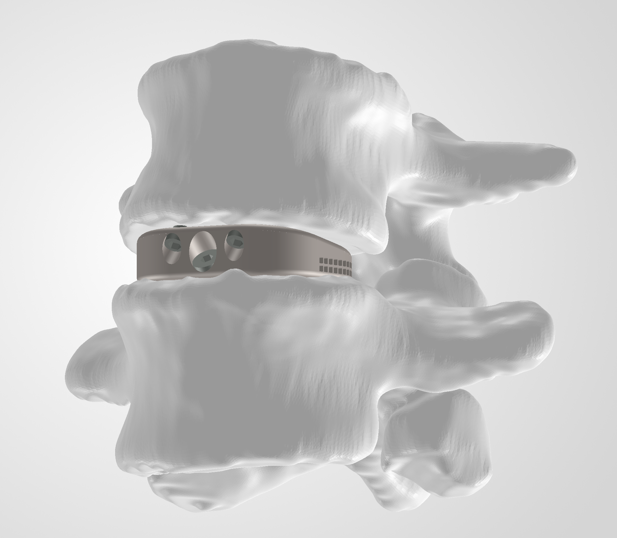
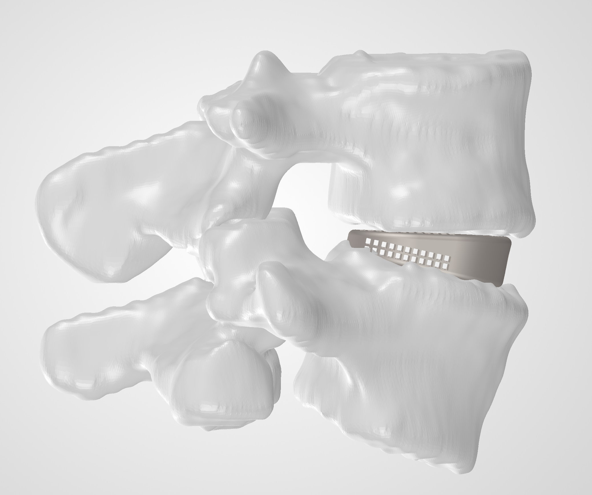
- Combined the L4 and L5 anatomy, cage, and fixation components into the final assembly to visualize the complete concept.
Final Design
These screens are interactive, move the models around to get a good look!
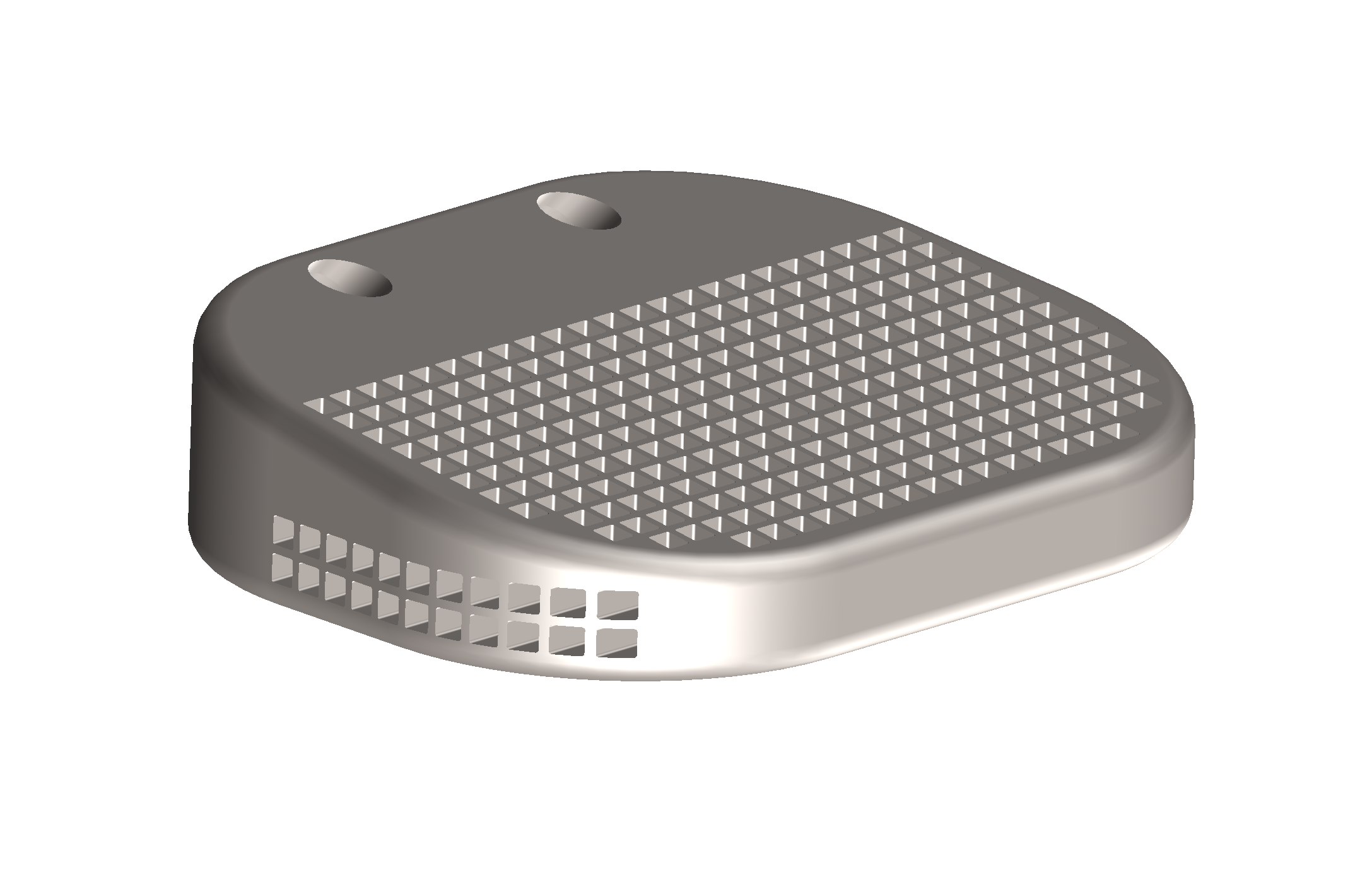
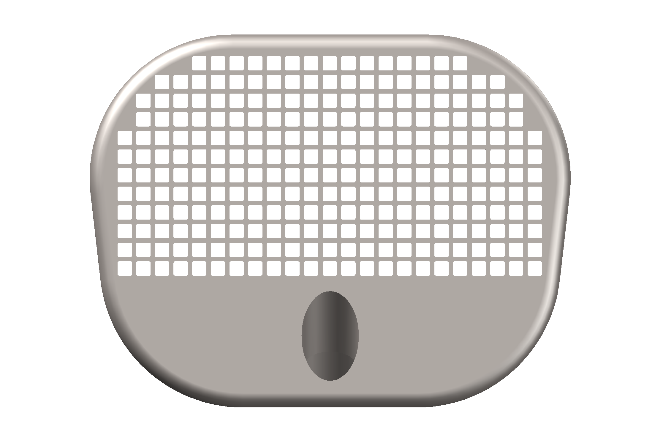
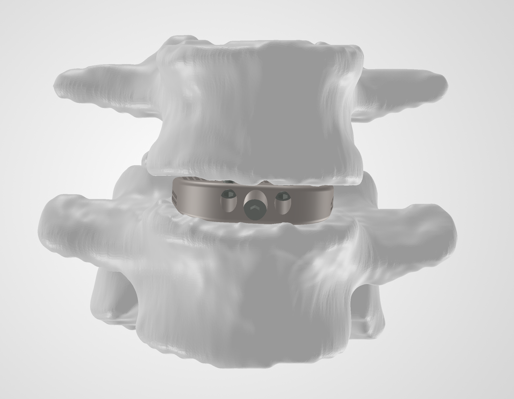
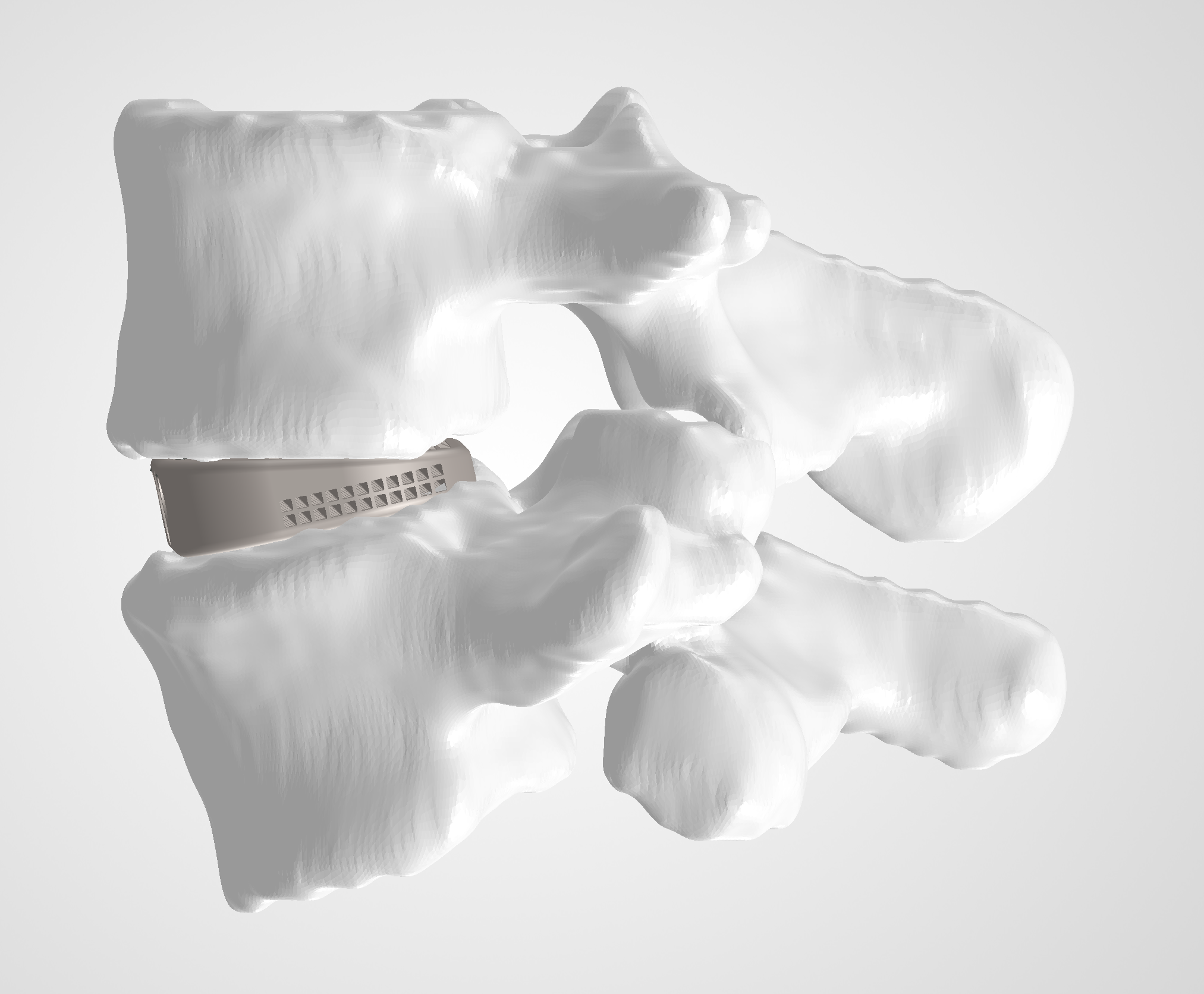
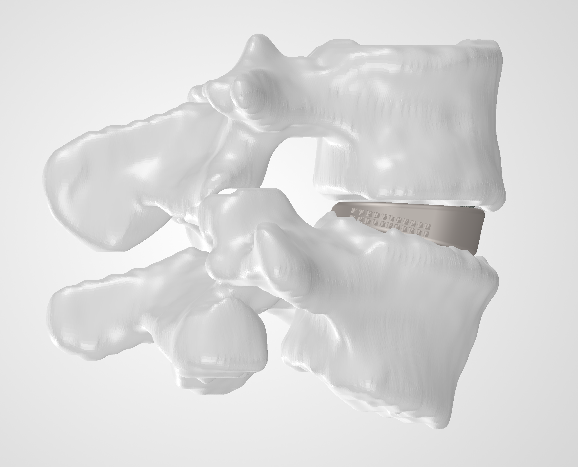
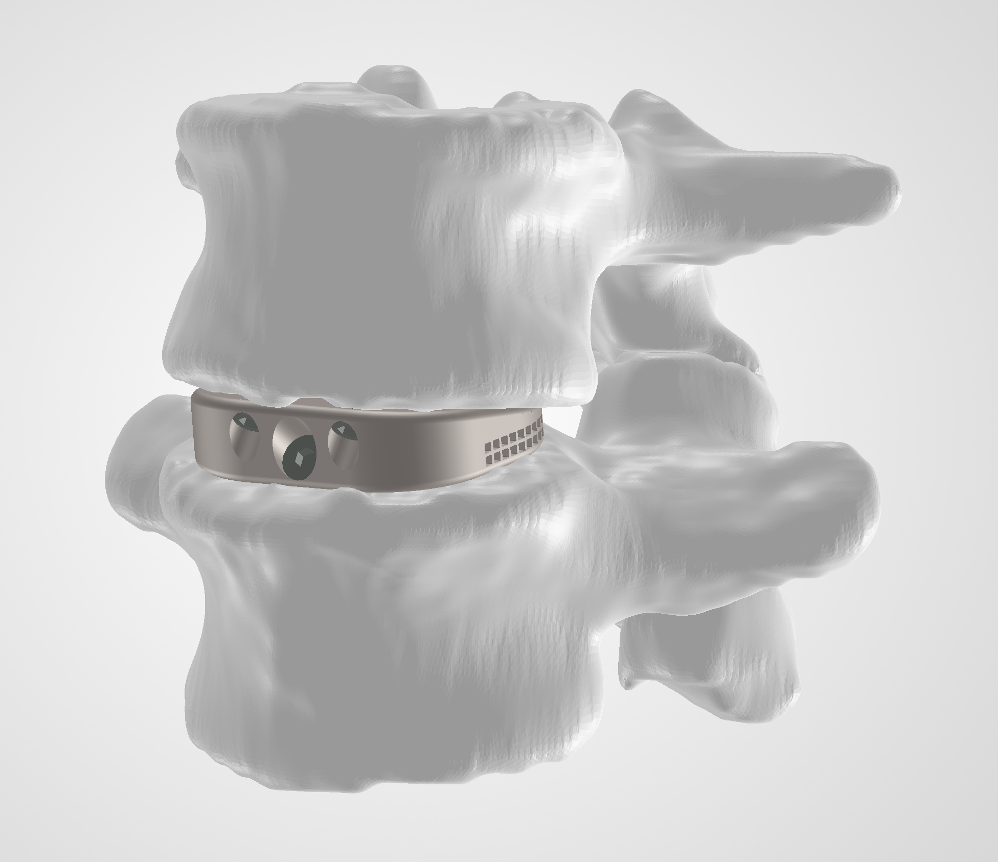
The completed project includes:
- Interactive 3D model of the cage
- Interactive 3D model of the L4–L5 assembly with cage and fixation screws
- Assembly animation
- Dimensioned engineering drawing with section views
- Final CAD imagery
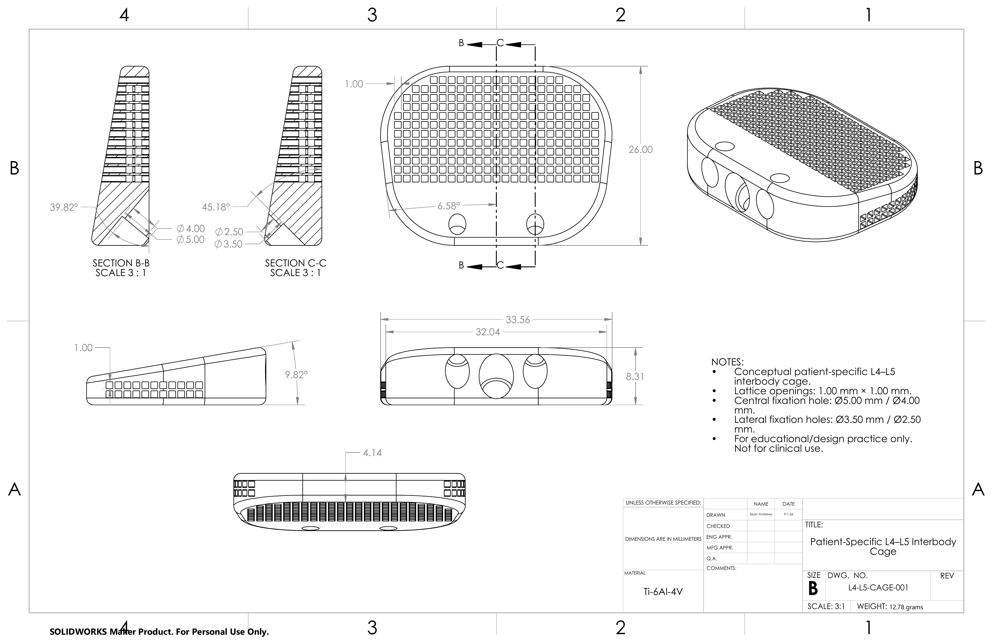
The engineering drawing documents the primary cage geometry, including its overall dimensions, wedge and footprint angles, lattice opening size, fixation-hole diameters and trajectories, and section views through both fixation-hole configurations.
Reflection
This project gave me experience working through a CAD workflow that started with medical imaging rather than a predefined engineering drawing. I had to interpret anatomy, decide which measurements mattered, translate them into design constraints, and continually evaluate the part within the anatomical assembly.
It also gave me hands-on practice with a wide range of SolidWorks tools, including sketch relationships, construction geometry, extrusions, cut-extrudes, fillets, reference planes, linear patterns, assemblies, mates, section views, materials, technical drawings, and animation.
The largest opportunity for improvement is moving from a conceptual model to a more clinically and mechanically informed implant. The lattice geometry, fixation system, cage footprint, and anatomical fit would all need considerably more engineering analysis and validation before this could function as anything beyond a concept.
My next step is to get feedback from engineers and product designers working in spine and medical devices, to make my SolidWorks workflow more efficient and my design methodology more representative of actual patient-specific implant development.
What I Could Improve On
- Incorporate more detailed endplate surface geometry to improve conformity and contact across the implant footprint. On the right side of my model, the cage didn’t fully fill the endplate area, leaving a small gap and making one of the screws slightly visible, as if that region wasn’t fully fused. I’d like to better understand that surface geometry so I can design a more detailed cage with fuller contact across the entire footprint.
- Go deeper on the lattice design itself. I tried to replicate the look of the 3D-mesh/lattice structures I see on many spinal fusion cages by repeating cut-extrude patterns in the same general shape, but I know the actual lattice geometry behind real cages is far more complex and tailored differently for each patient. In a future iteration I’d like to learn how to determine which lattice structure fits a specific patient’s anatomy, and how to model it more efficiently.
- Use AI tools in the workflow. Many spine companies use AI to help generate 3D segmentations from CT data and to help curate the fusion cage design for the defected area. I created my segmentations by hand in 3D Slicer, and I’d like to learn how to integrate AI into that process and test it out on several CT scans.
- Add surface texturing to the cage. My model currently has a relatively smooth surface, but modern spinal cages are deliberately engineered with a textured, micro-rough, or porous finish. That roughness serves two purposes: primary stability, by immediately gripping the endplates and resisting migration right after implantation, and secondary stability, since bone tissue can't anchor well to a smooth surface but integrates much more readily with a rough or porous one that mimics natural bone structure. In a future iteration I'd want to move away from a smooth finish and design in that kind of surface texture.